Milling Tool Assembly Having a Replaceable Cutter

a technology of milling tool and cutter, which is applied in the direction of shaping cutter, manufacturing tools, transportation and packaging, etc., can solve the problems of inconvenient use, inconvenient production, and all the above described solutions suffer from restrictive production requirements,

Active Publication Date: 2012-01-12
KENNAMETAL INC
View PDF4 Cites 43 Cited by
  • Summary
  • Abstract
  • Description
  • Claims
  • Application Information

AI Technical Summary

Problems solved by technology

However the increasing global pricing of modern tool alloys along with recently developed intricate surface treatment, made it less economical, as the expensive shank material was wasted.
The described pilot, concentric aligner, pilot bore and concentric bore, are necessary because the threaded coupler by its own is not sufficiently accurate for such repeated replacement of cutters.
Nevertheless all the above described solutions suffer from restrictive production requirements.
Furthermore, sintered carbi...

Method used


Image

  • Milling Tool Assembly Having a Replaceable Cutter
  • Milling Tool Assembly Having a Replaceable Cutter
  • Milling Tool Assembly Having a Replaceable Cutter

Examples


first embodiment

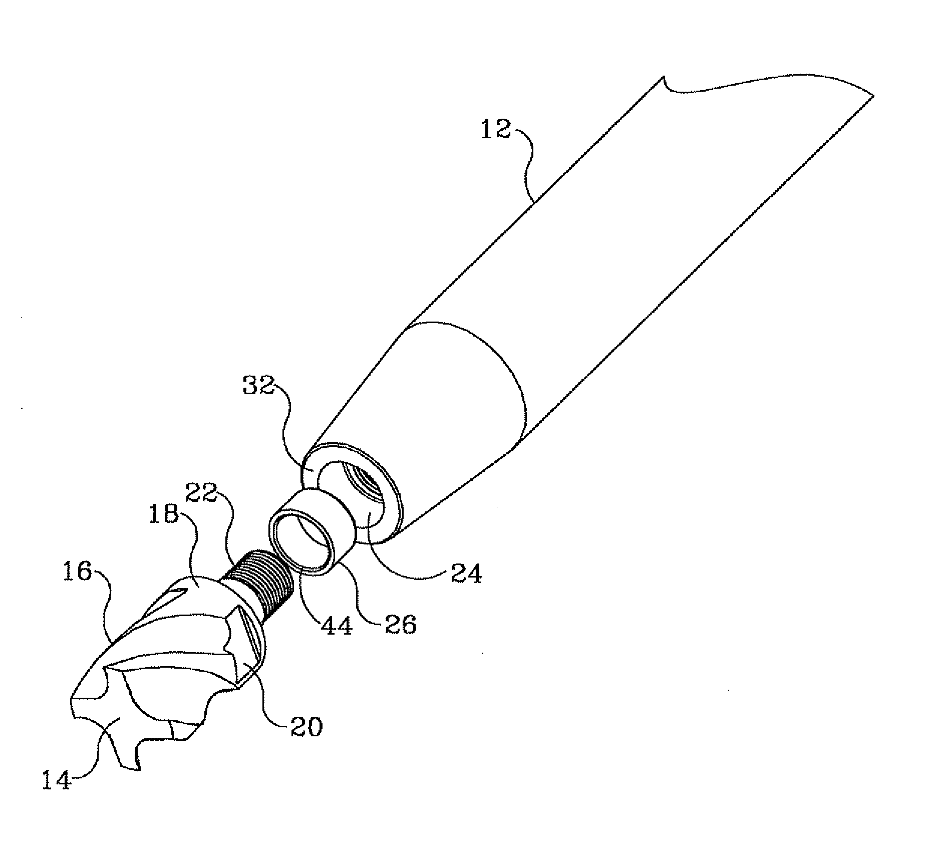
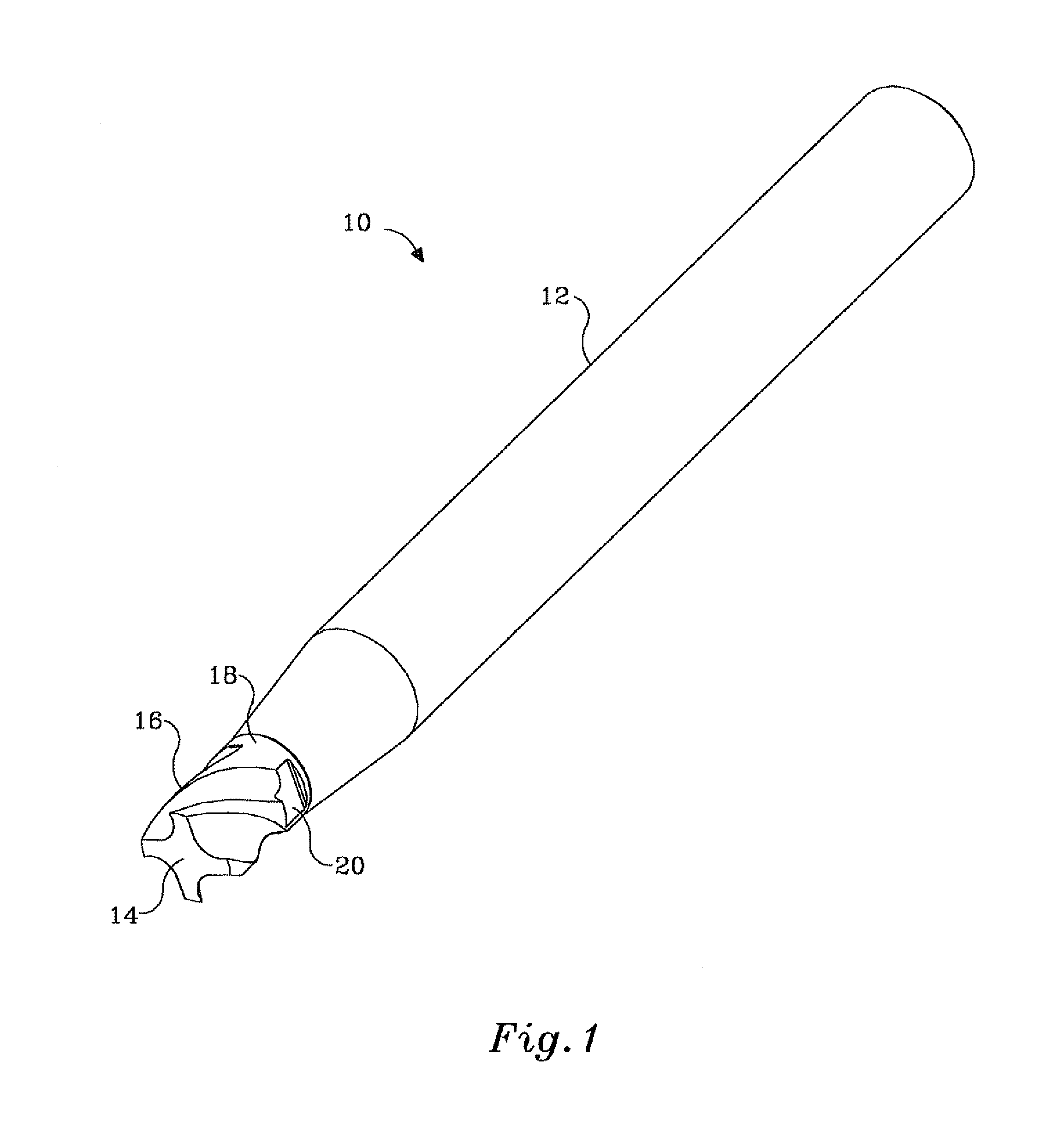
[0024]FIG. 1 shows a milling tool assembly generally referenced 10 according to the invention, comprising a reusable shank 12 and replaceable cutter 14, coupled by a detachable joint. The visible portion of the cutter 14 may include an active fluted portion 16, followed by a short cylindrical portion 18. The cylindrical portion 18 is preferably equipped with at least two opposing parallel flats 20, on which a standard spanner may fit. The shank 12 is shown here cylindrical with a tapered portion, by way of example only, it being understood that other cross-sections and shapes are also possible. The cutter 14, shown here as an end mill may be replaced with a face mill, rounded tip mill, slitting mill, drill, reamer, or any other replaceable tip for milling, drilling, reaming or other metal cutting applications.

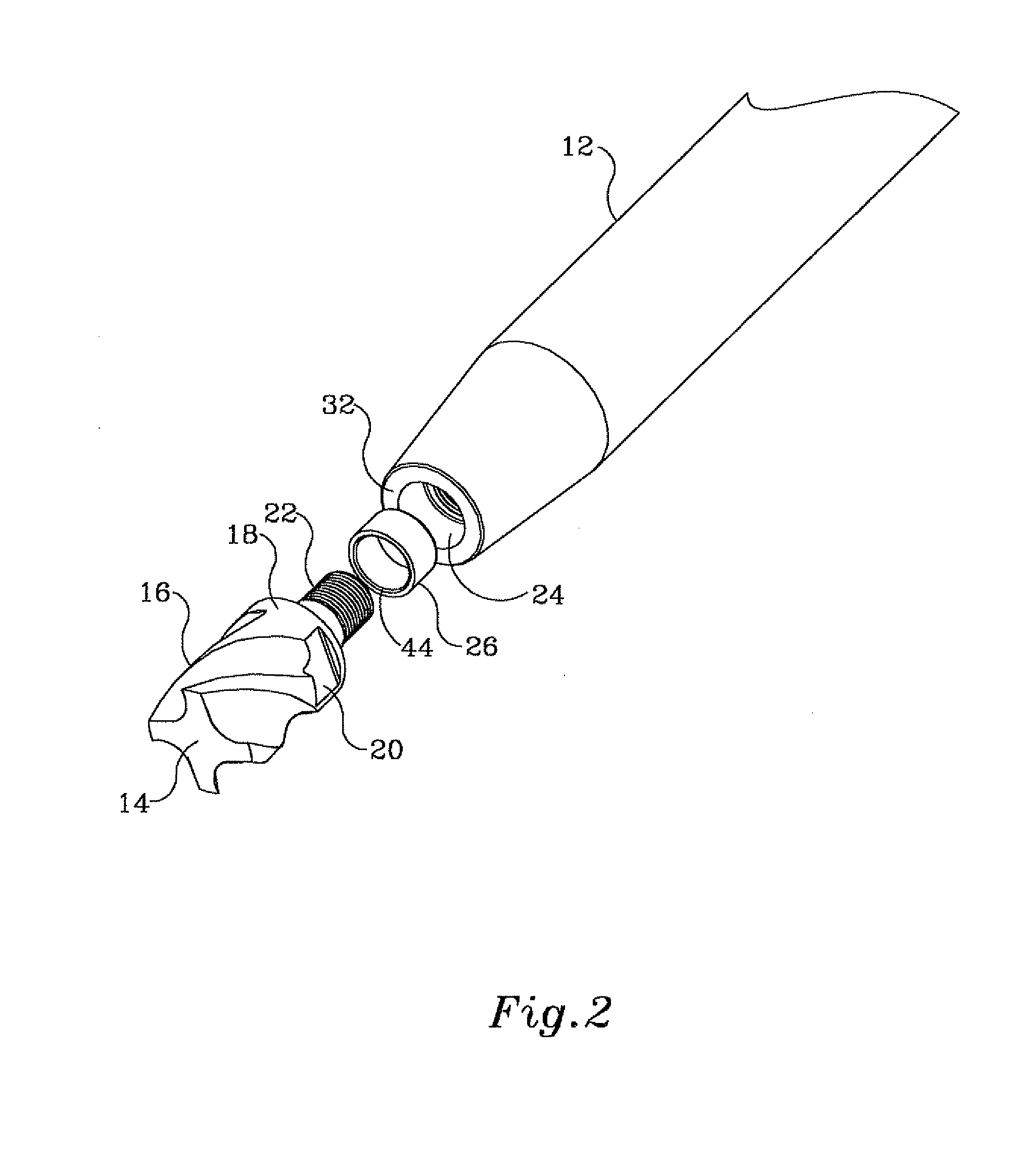
[0025]FIGS. 2 and 3 are exploded views of the milling tool assembly 10, revealing some details of the joint, such as an outwardly protruding threaded tail 22 of the cutter 14, ...

second embodiment

[0033]In the above-described embodiment, the intermediate alignment sleeve 26, being a plain sleeve, operates only in the radial direction, while the axial position is derived from the direct contact of stop shoulder 30 of the cutter 14 with the axial stop surface 32 of the shank 12. FIG. 5 shows a second embodiment where the intermediate alignment sleeve 36 is in the form of a flanged sleeve, such that the axial stop shoulder 30 of the cutter 14 does not make direct contact with the axial stop surface 32 of the shank 12, but rather the axial stop shoulder 30 and the axial stop surface 32 abut respective front and rear surfaces of the sleeve flange 38, providing vibration and shock absorption in both the axial and radial directions.

[0034]FIG. 6 shows yet a further embodiment where the longitudinal cross-section of the intermediate alignment sleeve 40 is in the form of a corrugated sleeve that may be made from metal, while preserving the elasticity of the plastic sleeves described ab...


PUM

PropertyMeasurementUnit
Thicknessaaaaaaaaaa
Diameteraaaaaaaaaa
Strengthaaaaaaaaaa

Abstract

A milling tool assembly has a replaceable cutter and a reusable shank connected to the cutter with a detachable joint. The joint may be, for example, a threaded connection. An intermediate alignment sleeve made of an elastic or semi-elastic material, is positioned between the cutter and the shank about the axis of rotation of the shank.

Description

FIELD OF THE INVENTION[0001]The present invention relates to a milling tool assembly, and in particular to the joint of a replaceable round tip to a reusable shank, by means of a partially elastic energy absorbing joint.BACKGROUND OF THE INVENTION[0002]Historically, end mills for metal cutting machinery were produced as a single unit, comprising a fluted cutting portion and a cylindrical or conical shank portion sized to fit a machine spindle. However the increasing global pricing of modern tool alloys along with recently developed intricate surface treatment, made it less economical, as the expensive shank material was wasted. It is therefore became common practice to produce a separate cutter made of high quality alloy or sintered carbide, which is then concentrically attached to the end of a reusable steel shank.[0003]It is highly desirable that the cutter be easily replaced, upon wear, while leaving the shank in the machine spindle, such that no further adjustments are required ...

Claims


Application Information

Patent Timeline
IPC IPC(8): B23C5/20B23C5/22B23B51/00B23C5/10
CPCB23B31/11B23B2231/0204B23B2251/02B23C5/10B23C2210/02Y10T407/1924Y10T407/1908Y10T408/76Y10T408/90993Y10T407/28B23C2250/12
Inventor SHARIVKER, LEONID B.VOLOKH, VLADIMIR D.BOULAKHOV, SERGEI V.ZEIDNER, SHAYGALIPKO, VLADIMIR
Owner KENNAMETAL INC
Why Eureka
Try Eureka