Reaction-type turbine
a turbine type and reaction technology, applied in reaction engines, impulse engines, non-positive displacement engines, etc., can solve the problems of impact or reaction that drives the shaft to rotate, and achieve the effect of reducing manufacturing costs, reducing energy loss, and maintaining the stability of steam turbines
- Summary
- Abstract
- Description
- Claims
- Application Information
AI Technical Summary
Benefits of technology
Problems solved by technology
Method used
Image
Examples
second exemplary embodiment
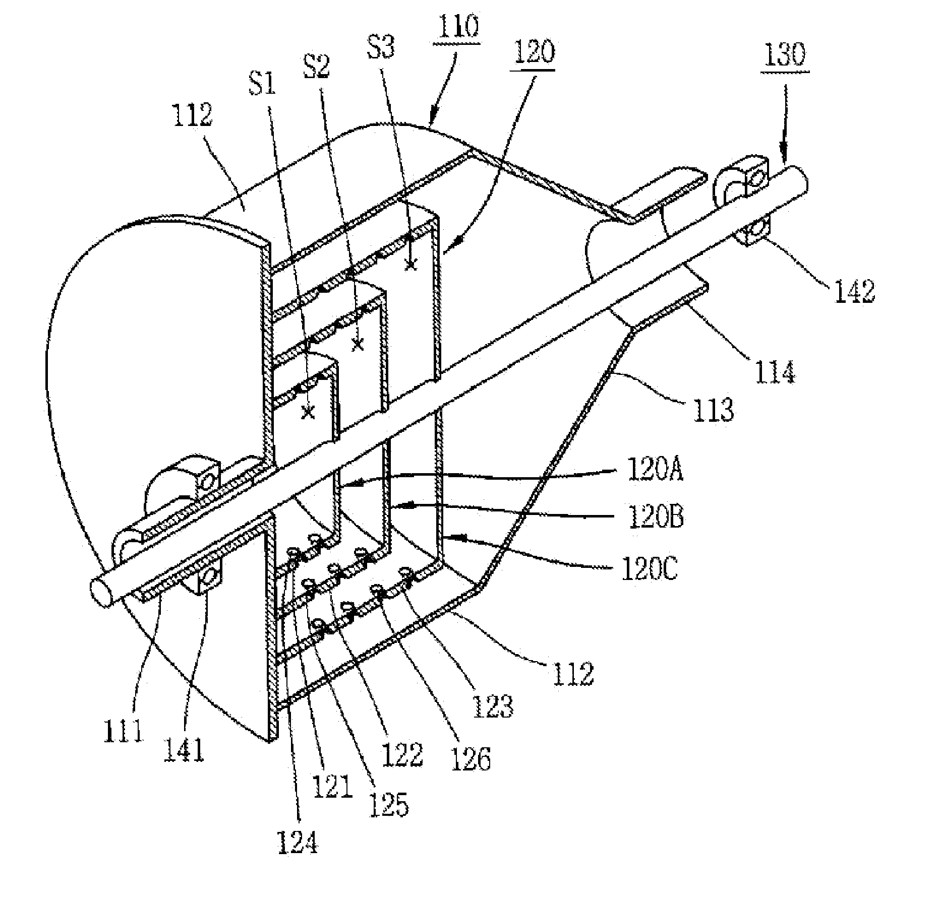
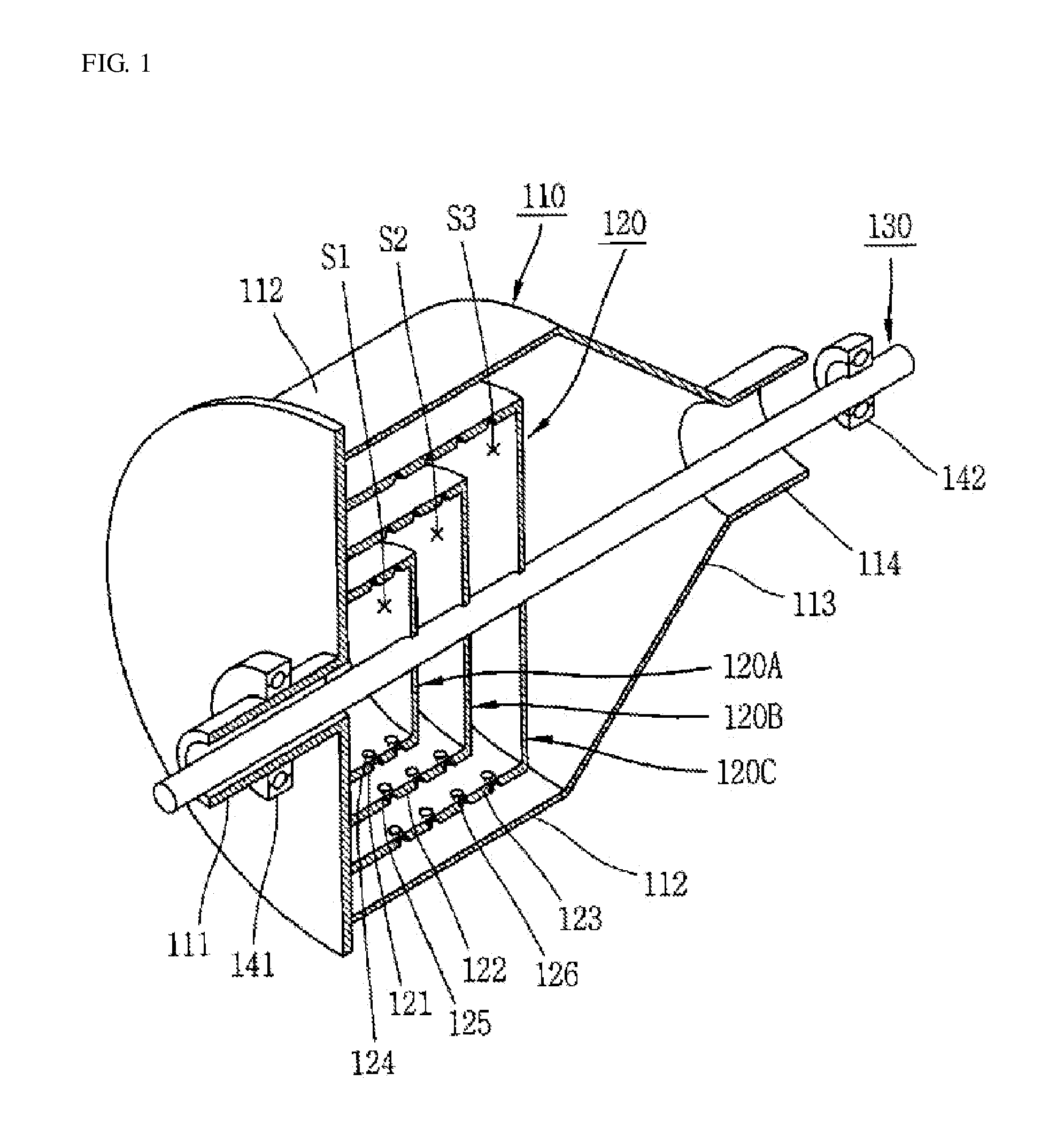
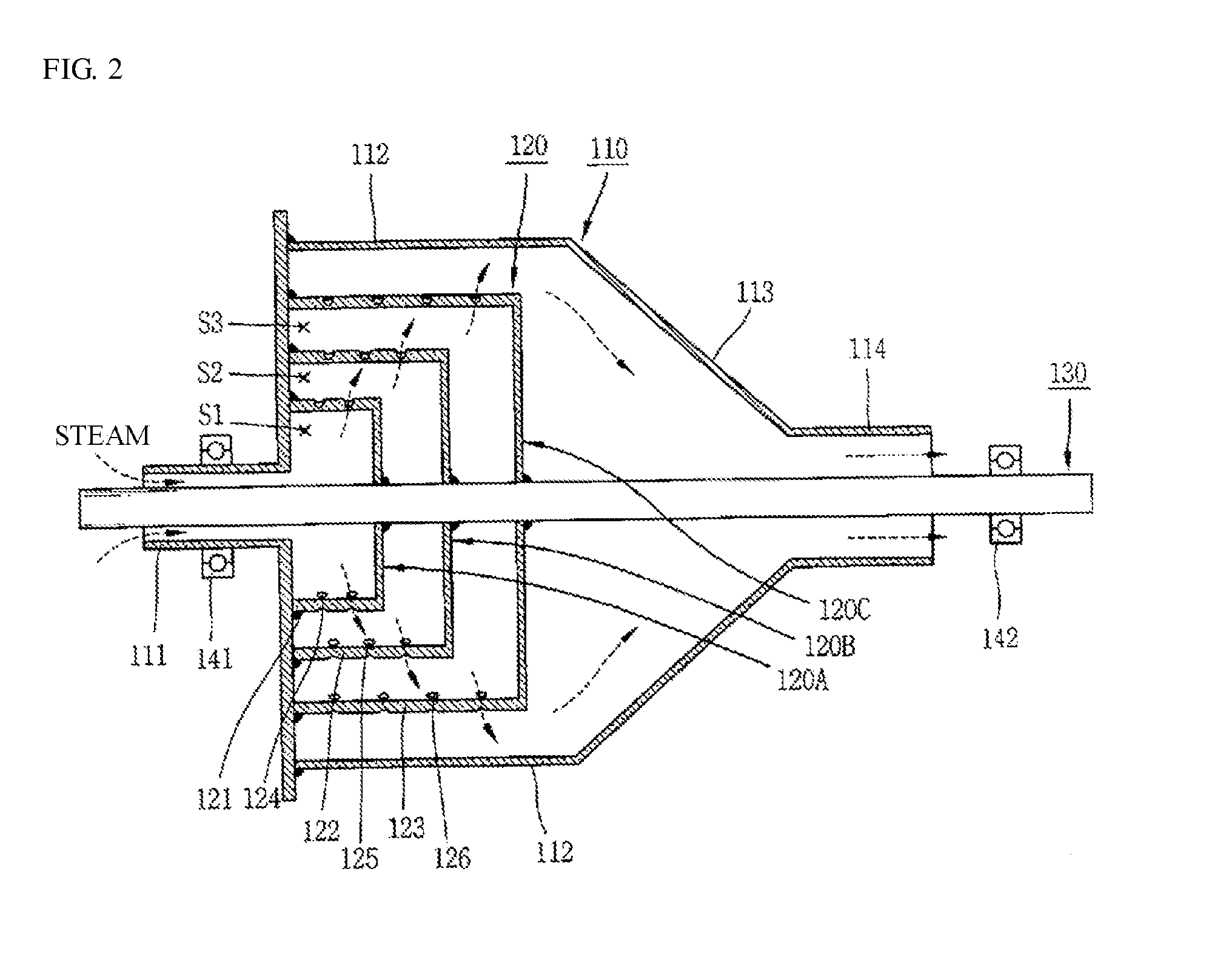
[0044]According to the first exemplary embodiment, the turbine shaft 130 penetrates through the housing 110 and has one side supported by the first bearing 141 while one side of the housing 110 is supported by the second bearing 142, whereas according to the second exemplary embodiment, as shown in FIG. 14, the turbine shaft 130 penetrating the housing 110 has both ends supported by the respective first and second bearings 141 and 142.
[0045]In this case, one end of the turbine shaft 130 may be supported by the first bearing 141 at an outer edge of the outlet 114, or in some cases, may be supported by the first bearing 141 between the turbine shaft 130 and the outlet 114 of the housing 110. Here, if the first bearing 141 is disposed at the outer edge of the outlet 114, the outlet 114 is formed as a cylindrical shape. On the other hand, if the first bearing 141 is interposed between the turbine shaft 130 and the outlet 114, the outlet 114 may have a plurality of ribs 114a formed radia...
third exemplary embodiment
[0047]In the first and second exemplary embodiments as described above, the turbine shaft 130 penetrates through the housing 110 and is supported by the first bearing 141, while in the third exemplary embodiment, one end of the turbine shaft 130 is welded to the third jet and rotating unit 120C inside the housing 110, and the other end of the turbine shaft 130 is rotatably supported by the first bearing 141, as illustrated in FIG. 15. In the third exemplary embodiment, the inlet 111 is extruded in one side of the housing 110 and rotatably supported by the second bearing 142.
[0048]Other configurations and effects of the third exemplary embodiment are similar to those of the first and second exemplary embodiments as described above, and accordingly a detailed description thereof will be omitted. In the steam turbine according to the third exemplary embodiment, as illustrated in FIG. 15, since the turbine shaft 130 is welded only to the third jet and rotating unit 120C, the assembly pr...
fourth exemplary embodiment
[0049]In the first, the second, and the third exemplary embodiments as described above, the turbine shaft 130 provided separately from the housing 110 is coupled with the housing 110 in a manner to penetrate through the housing 110, while in the fourth exemplary embodiment, the turbine shaft 130 is integrated with the housing 110, as illustrated in FIG. 16. For example, by extending the inlet 11 and outlet 114 of the housing 110 and coupling the outlet 114 with an external device, propulsion force generated by the first, the second, and the third jet and rotating units 120A, 120B, and 120C is transferred to the external device through the housing 110. That is, the housing 110 is endued with the function of the turbine shaft 130.
[0050]Other configurations and effects of the fourth exemplary embodiment are similar to those of the first through third exemplary embodiments as described above, and accordingly a detailed description will be omitted. Since the steam turbine according to th...
PUM
 Abstract
Description
Claims
Application Information
 - R&D
- Intellectual Property
- Life Sciences
- Materials
- Tech Scout
- Unparalleled Data Quality
- Higher Quality Content
- 60% Fewer Hallucinations
Browse by: Latest US Patents, China's latest patents, Technical Efficacy Thesaurus, Application Domain, Technology Topic, Popular Technical Reports.
© 2025 PatSnap. All rights reserved.Legal|Privacy policy|Modern Slavery Act Transparency Statement|Sitemap|About US| Contact US: help@patsnap.com


