Multiblade fan

Inactive Publication Date: 2012-01-12
MITSUBISHI ELECTRIC CORP
View PDF3 Cites 15 Cited by
  • Summary
  • Abstract
  • Description
  • Claims
  • Application Information

AI Technical Summary

Benefits of technology

[0013]In a multiblade fan according to an aspect of the present invention, a space between an inlet and an impeller increases from a rotation axis of the impeller toward an outlet of a casing. This configuration permits air that has flown into the impeller through the inlet to flow in a gentle curve inside the impeller to pass through between blades. This causes velocity distribu

Problems solved by technology

Because this causes the velocity of flow to be likely to fluctuate, pressure differential of air or a level of air turbulence increases, which can result in louder noise or degradation in blowing performance.
Because this causes the impeller to function insufficiently, it is possible that the multiblade fan provides its blowing performance insufficiently.
However, these configurations are disadvantageous in

Method used


Image

  • Multiblade fan
  • Multiblade fan
  • Multiblade fan

Examples


Example

[0026]Exemplary embodiments of the present invention are described in detail below with reference to the accompanying drawings. The present invention is not limited to the exemplary embodiments. Elements of the embodiments include all equivalents that do not depart from the spirit and scope of the invention in its broadest form. The plurality of modifications of the embodiments mentioned below can be arbitrarily combined within the range that will occur to those skilled in the art.

[0027][Multiblade Fan]

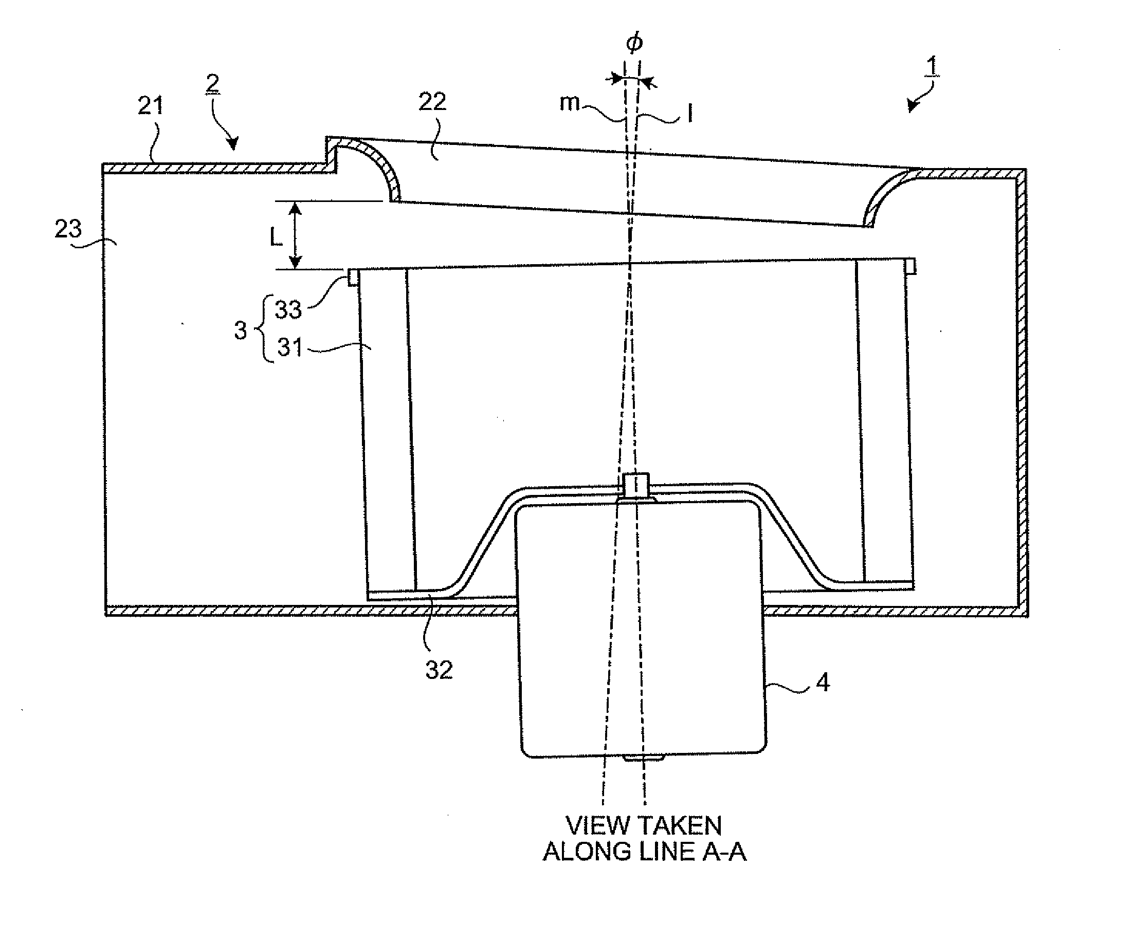
[0028]A multiblade fan 1 is a blower that includes a multibladed wheel (sirocco fan). The multiblade fan 1 is applied to, for example, an air conditioning system, a duct fan, and a ventilating fan. The multiblade fan 1 can be of a single inlet type or a double inlet type. In the present embodiment, the multiblade fan 1 of a single inlet type will be described as an example.

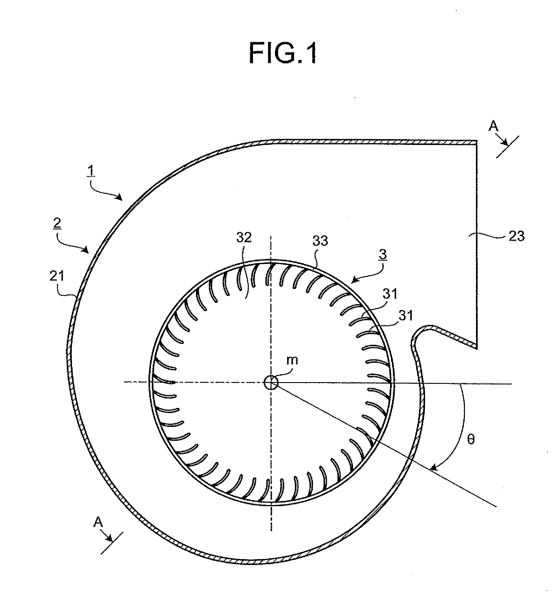
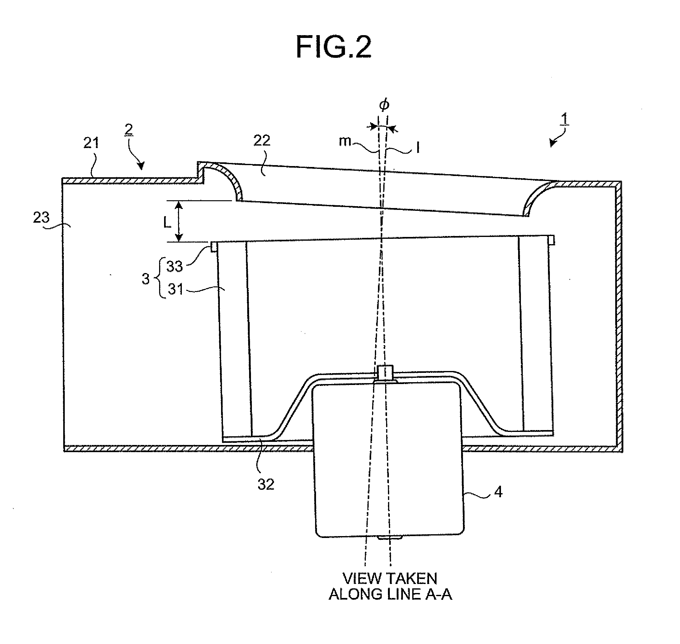
[0029]The multiblade fan 1 includes a casing 2, an impeller 3, and a drive motor 4 (see FIG. 1 and FIG. 2).

[0030]...


PUM


Abstract

To provide a multiblade fan that enables an improvement in noise characteristics or blowing performance. The multiblade fan includes a scroll type casing that has a bell-mouthed inlet and an impeller housed in the casing. The impeller includes a plurality of blades and a rotation axis m oriented toward the inlet of the casing. The blades are annularly arranged. In the multiblade fan, a center axis of the inlet and the rotation axis of the impeller are arranged at a tilt angle to each other and in any one of an intersecting positional relationship and a skew-lines positional relationship so that a space between the inlet and the impeller increases from the rotation axis of the impeller toward an outlet of the casing.

Description

TECHNICAL FIELD[0001]The present invention relates to a multiblade fan, and more particularly, to a multiblade fan capable of improving noise characteristics or blowing performance.BACKGROUND ART[0002]A typical multiblade fan includes a scroll type casing having a bell-mouthed inlet and an impeller housed in the casing. The impeller is a multiblade impeller (sirocco fan) that includes a plurality of annularly arranged blades and that is housed in the casing with a rotation axis of the impeller oriented toward the inlet of the casing.[0003]In a structure where a center axis of the inlet and the rotation axis of the impeller are coaxially arranged, an inertial force is exerted on air flown into the impeller through the inlet. Hence, airflow inside the impeller is likely to be deflected toward a main plate (a plate that supports blades). Then, the velocity distribution (velocity distribution of air blowing out of the spaces between the blades) of the air passing through between the bla...

Claims


Application Information

Patent Timeline
IPC IPC(8): F01D1/06
CPCB60H1/00471F04D29/162F04D29/441F04D29/4226F04D29/4213F05D2250/51F04D17/08F04D29/44F04D29/66F04D29/054
Inventor OKAMOTO, KAZUKISAKODA, KENICHIKIKUCHI, HITOSHI
Owner MITSUBISHI ELECTRIC CORP
Why Eureka
Try Eureka