Variable gain amplification device

a gain amplification and variable gain technology, applied in the direction of gain control, high frequency amplifiers, rf amplifiers, etc., can solve the problems of general proportionality of deterioration of distortion characteristics, weak desired radio waves may exist in strong jamming, fluctuation of 1 db compression points, etc., to suppress the deterioration of noise characteristic generated

Inactive Publication Date: 2011-04-21
RENESAS ELECTRONICS CORP
View PDF0 Cites 9 Cited by
  • Summary
  • Abstract
  • Description
  • Claims
  • Application Information

AI Technical Summary

Benefits of technology

[0013]The present invention provides the variable gain amplification device that suppresses the deterioration of the noise characteristic generated according to the amount of attenuation by fixing the amount of attenuation while the variable gain amplification unit is changing the gain.

Problems solved by technology

Further, a weak desired radio wave may exist in a strong jamming.
Specifically, there is a problem of fluctuating a 1 dB compression point.
However the deterioration of the distortion characteristic is generally proportional to the amount of attenuation of the fixed attenuator.
It is known that such problem occurs in the method to switch control current of the gain amplifier using the fixed attenuator.
The amplifier using such method cannot have both of the wide gain range and the low distortion characteristic.
However, in that case, the present inventor has found a problem that noise characteristic deteriorates.
Generally, if an attenuator is connected to a previous stage of an amplifier, and a gain is reduced by changing the amount of attenuation, the noise characteristic will also deteriorate in proportion to the amount of attenuation.
Therefore, the noise characteristic of the variable gain amplification device of FIG. 20 largely deteriorates in the region where the maximum gain state is obtained as compared to the amplifier of FIG. 16.

Method used


Image

  • Variable gain amplification device
  • Variable gain amplification device
  • Variable gain amplification device

Examples


first exemplary embodiment

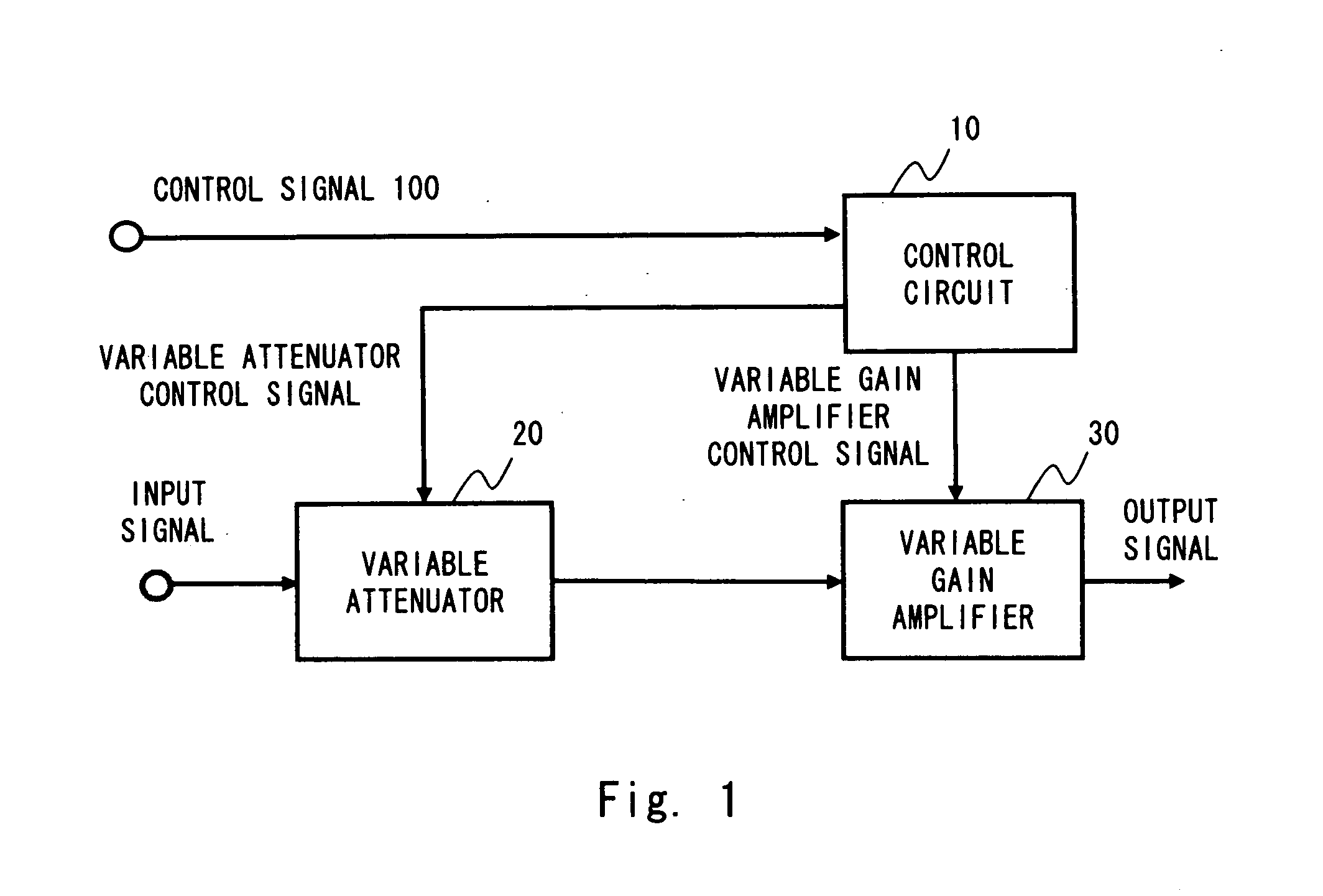
[0041]Hereinafter, exemplary embodiments of the present invention are described with reference to the drawings. A configuration example of a variable gain amplification device according to a first exemplary embodiment of the present invention is explained with reference to FIG. 1. The variable gain amplification device includes a control circuit 10, a variable attenuator 20, and a variable gain amplifier 30.

[0042]The control circuit 10 receives a control signal 100, and generates a variable attenuator control signal, which is output to the variable attenuator 20 according to the control signal 100, and a variable gain amplifier control signal, which is output to the variable gain amplifier 30. The control signal may be a control voltage composed of a voltage, for example. The variable attenuator 20 receives an input signal and attenuates the input signal. The input signal is to be attenuated and controlled of its gain to obtain the gain. The variable attenuator 20 outputs the attenu...

second exemplary embodiment

[0052]Next, a configuration example of a variable gain amplification device according to a second exemplary embodiment of the present invention is explained with reference to FIG. 5. In addition to the configuration of FIG. 1, the variable gain amplification device according to the second exemplary embodiment of the present invention further includes a variable gain amplifier 40 and an summer unit 50.

[0053]The variable gain amplifier 40 receives an input signal, is controlled by a second variable gain amplifier control signal obtained from the control circuit 10, and outputs the input signal with controlled gain to the summer unit 50.

[0054]The summer unit 50 adds the output signals with amplified gain which are obtained from the variable gain amplifier 30 and the variable gain amplifier 40. Then, an output signal of the variable gain amplification device is generated.

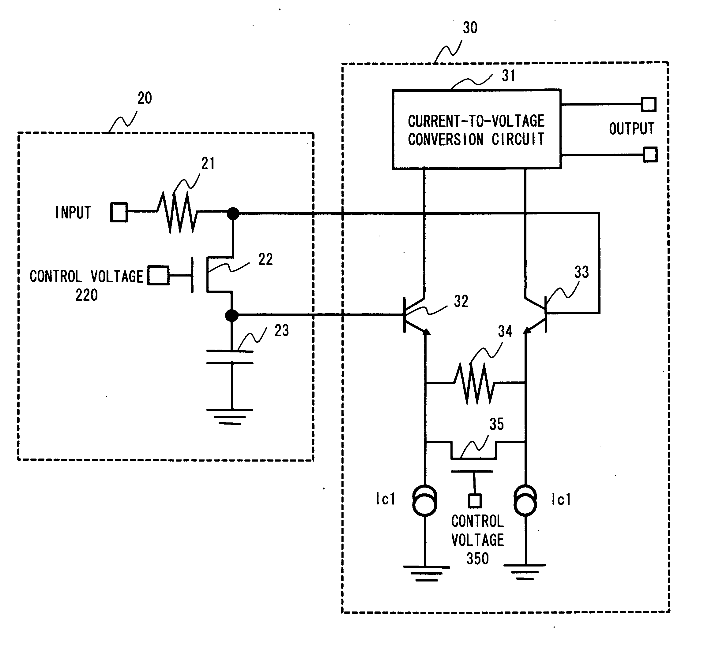
[0055]Next, a configuration example of the variable attenuator 20, and the variable gain amplifiers 30 and 40 of the ...

third exemplary embodiment

[0060]Next, a configuration example of the control circuit 500 according to a third exemplary embodiment of the present invention is explained with reference to FIG. 7. The control circuit 10 can be composed by using the control circuit 500. The control circuit 500 includes a power supply unit 11, a current-to-voltage conversion circuit 12, an operational amplifier 13, a MOS transistor 14, a bias power supply 15, and a MOS transistor 16. The current-to-voltage conversion circuit 12, the MOS transistor 14, and the bias power supply 15 are connected in series between the power supply unit 11 and a GND power supply. Further, the operational amplifier 13 receives a voltage at a node of the MOS transistor 14 and the current-to-voltage conversion circuit 12, and the control voltage 130, and outputs a gate voltage to the MOS transistor 14 and the MOS transistor 16. In this configuration, the MOS transistor 16 is to be controlled, and the MOS transistor 14 operates as a replica of the MOS t...


PUM


Abstract

Provided is a variable gain amplification device that suppresses deterioration of a noise characteristic generated according to an amount of attenuation by fixing the amount of attenuation while a variable gain amplification unit is changing a gain. The variable gain amplification device includes a variable attenuation unit that attenuates an input signal. The variable gain amplification device further includes a variable gain amplification unit that changes and amplifies a gain of the attenuated input signal which is output by the variable attenuation unit. A control unit is further included that controls to fix the amount of attenuation of the variable attenuation unit while the variable gain amplification unit is changing the gain.

Description

INCORPORATION BY REFERENCE[0001]This application is based upon and claims the benefit of priority from Japanese patent application No. 2009-241118 filed on Oct. 20, 2009, No. 2009-258093 filed on Nov. 11, 2009 and No. 2010-191851 filed on Aug. 30, 2010, the disclosure of which is incorporated herein in its entirety by reference.BACKGROUND[0002]1. Field of the Invention[0003]The present invention relates to a variable gain amplification device, and particularly to a variable gain amplification device that involves attenuation of an input signal.[0004]2. Description of Related Art[0005]In receivers such as a communication device and a TV, various reception radio wave statuses are assumed. Such a system receives signals of wide range signal strength. Therefore, the signal strength is adjusted to be appropriate signal strength by a variable gain amplification device, and then signal processes such as demodulation is performed. Thus, the variable gain amplification device requires a wide...

Claims


Application Information

Patent Timeline
Patent Type & Authority Applications(United States)
IPC IPC(8): H03G3/30
CPCH03F1/0261H03G3/3036H03F3/19H03F3/211H03F3/45085H03F3/45197H03F2200/411H03F2200/451H03F2203/21106H03F2203/21142H03F2203/45494H03F2203/45496H03F2203/45591H03F2203/45594H03G1/0023H03G1/0035H03F1/3205
Inventor OYABU, HIROKAZU
Owner RENESAS ELECTRONICS CORP
Why Eureka
Try Eureka