Sealing adapter for well tubing head

Inactive Publication Date: 2012-01-19
WHITE RICHARD +1
View PDF4 Cites 16 Cited by
  • Summary
  • Abstract
  • Description
  • Claims
  • Application Information

AI Technical Summary

Benefits of technology

[0005]The present invention provides advantages and alternatives over the prior art by providing a tubing head adapter which operates to provide a supplemental sealing barrier for a tubing head while maintaining access to the interior

Problems solved by technology

However, it has been found that tubing hangers may be susceptible to damage and/or may permit a pre

Method used


Image

  • Sealing adapter for well tubing head
  • Sealing adapter for well tubing head
  • Sealing adapter for well tubing head

Examples


Embodiment Construction

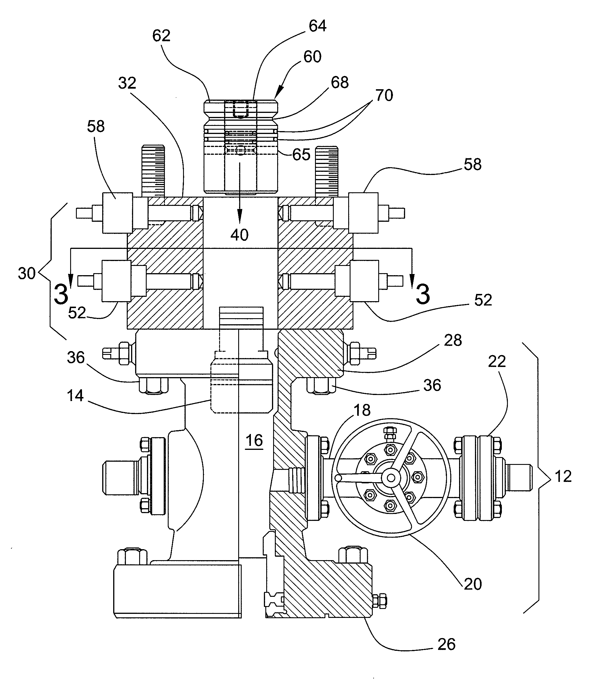
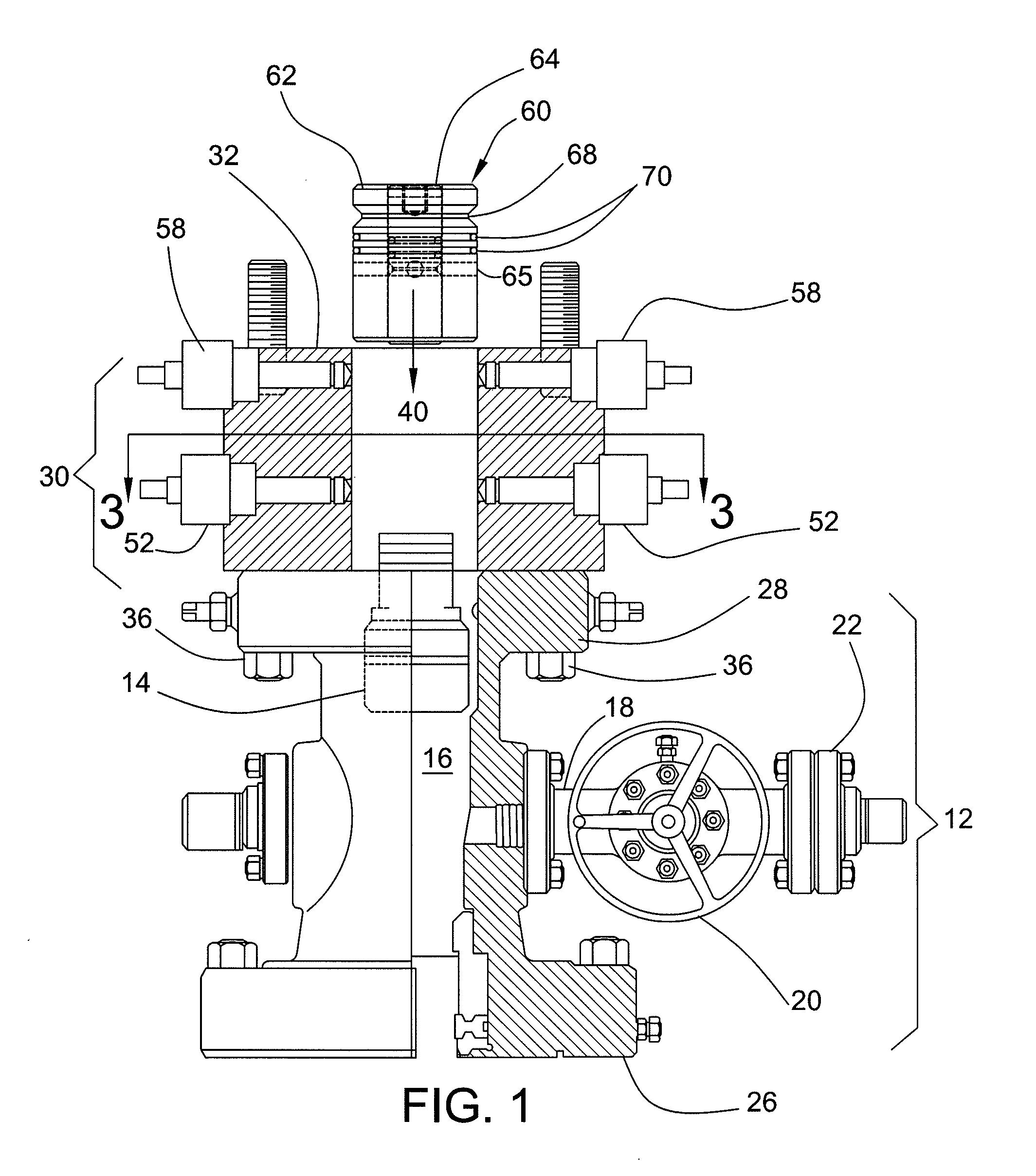
[0013]Reference will now be made to the drawings. To the extent possible, like elements are designated by like reference numerals in the various views. Referring to FIG. 1, a production tubing head 12 (also referred to as a tubing spool) is shown with a tubing hanger 14 in place within the axial bore 16 of the tubing head 12. In practice, the tubing head 12 is operatively connected to a well casing (not shown) in a manner as will be well known to those of skill in the art. As shown, the tubing head 12 may include a connection leg 18 for attachment of fracturing equipment or the like. In the illustrated exemplary arrangement, the connection leg 18 may be sealed by use of an isolation valve 20 and a flange seal 22. Thus, the tubing hanger 14 in combination with the isolation valve 20 and the flange seal 22 act to provide primary sealing of the production tubing head 12. However, other primary sealing arrangements may be used if desired.

[0014]In a typical arrangement, the production tu...


PUM


Abstract

A tubing head adapter which operates to provide a supplemental sealing barrier for a tubing head while maintaining access to the interior of the tubing head. The adapter includes an annular body adapted to be secured in fixed relation to the tubing head and a dummy hanger adapted to be matedly inserted into the annular body. The dummy hanger includes an annular sleeve insert and a removable axial plug disposed within the annular sleeve insert. A plurality of extendable and retractable locking pins secure the dummy hanger in place.

Description

TECHNICAL FIELD[0001]The present invention relates generally to barrier systems for wells, and more particularly, to a barrier system adapted to provide secondary protective sealing for a tubing head operatively engaging an oil or gas well.BACKGROUND OF THE INVENTION[0002]It is well known to increase production from oil and gas formations by so called “fracturing” to increase the permeability of the production zone. In general, fracturing involves pumping pressurized fluids through perforations in a well casing into a production zone in order to break or fracture pores in the production zone. In the fracturing procedure, fracturing fluids are pumped under very high pressures of about 5,000 to 10,000 psi through the perforations into the formation. The high pressure breaks the formation to form flow channels for hydrocarbon fluids. In practice, it is common to carry out fracturing procedures for a collective group of wells and to then seal some or all of those wells for a period of t...

Claims


Application Information

Patent Timeline
IPC IPC(8): E21B33/03
CPCE21B33/04E21B33/03
Inventor WHITE, RICHARDHOMFELD, ALFRED
Owner WHITE RICHARD
Why Eureka
Try Eureka