Nanofiber manufacturing apparatus and method of manufacturing nanofibers

Active Publication Date: 2012-01-19
PANASONIC INTELLECTUAL PROPERTY MANAGEMENT CO LTD
View PDF3 Cites 14 Cited by
  • Summary
  • Abstract
  • Description
  • Claims
  • Application Information

AI Technical Summary

Benefits of technology

[0028]According to the present invention, productivity o

Problems solved by technology

One of specific problems with an apparatus for manufacturing nanofibers by such electrostatic stretching is difficulty in increase in productivity.
However, although the production rate of nanofibers per unit a

Method used


Image

  • Nanofiber manufacturing apparatus and method of manufacturing nanofibers
  • Nanofiber manufacturing apparatus and method of manufacturing nanofibers
  • Nanofiber manufacturing apparatus and method of manufacturing nanofibers

Examples


embodiment

[0039]The following describes a nanofiber manufacturing apparatus and a method of manufacturing nanofibers according to the present invention with reference to the drawings.

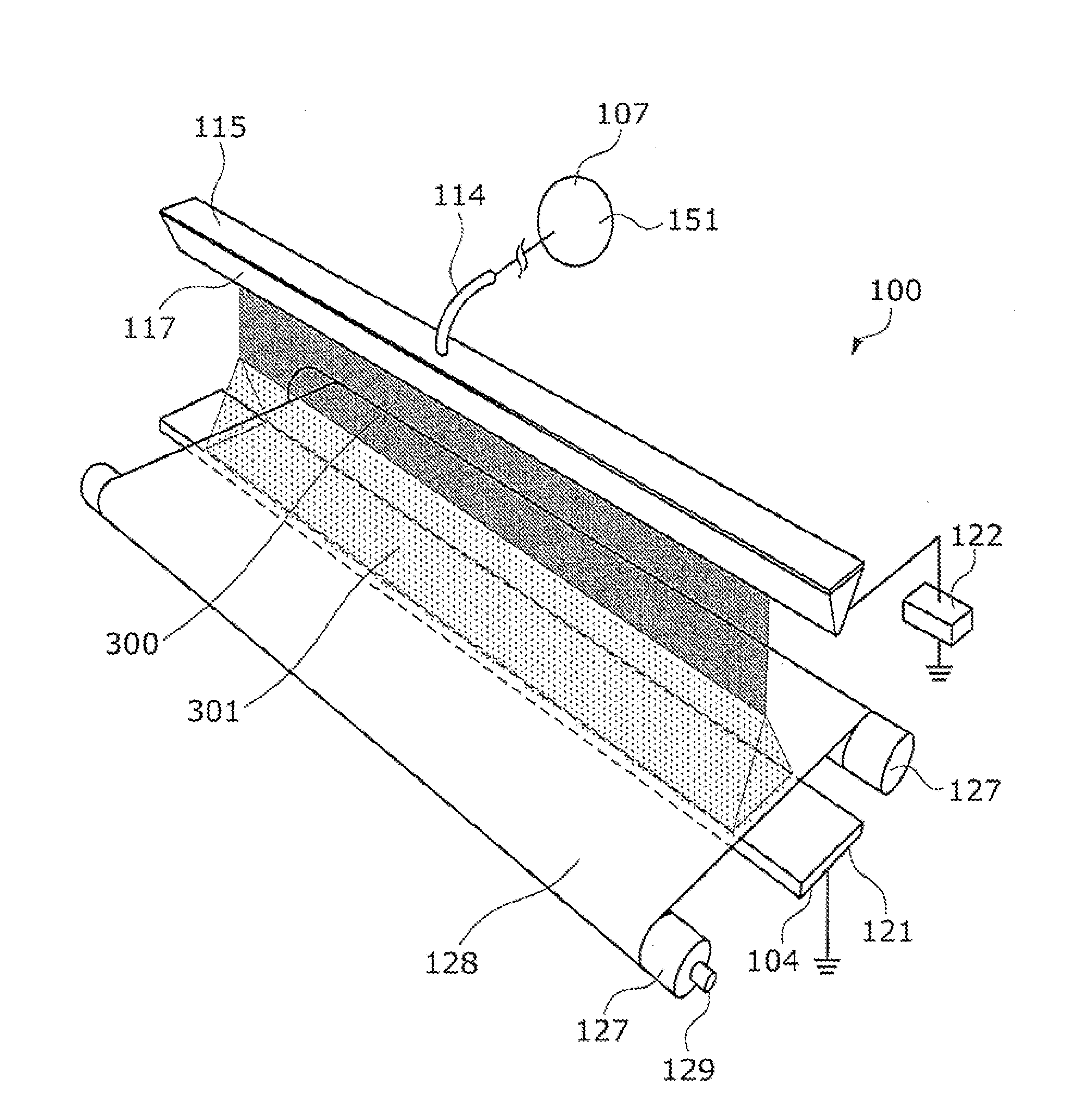
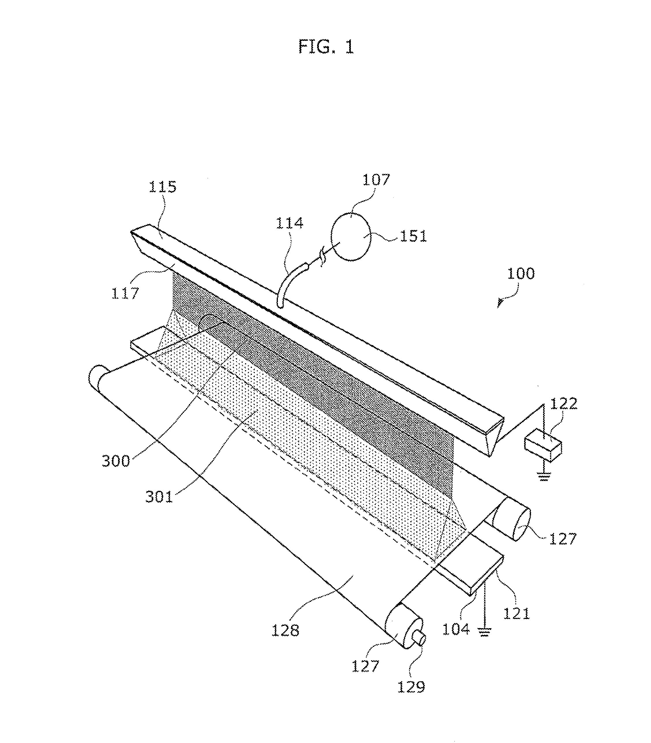
[0040]FIG. 1 is a perspective view illustrating a nanofiber manufacturing apparatus.

[0041]As shown in FIG. 1, a nanofiber manufacturing apparatus 100, which is an apparatus for manufacturing nanofibers 301 by electrically stretching a solution 300 in space, includes an effusing body 115, a supply unit 107, a charging electrode 121, and a charging power supply 122. In an embodiment of the present invention, the nanofiber manufacturing apparatus 100 further includes an accumulating unit 128 and an attracting unit 104. In addition, the nanofiber manufacturing apparatus 100 includes a moving unit 129.

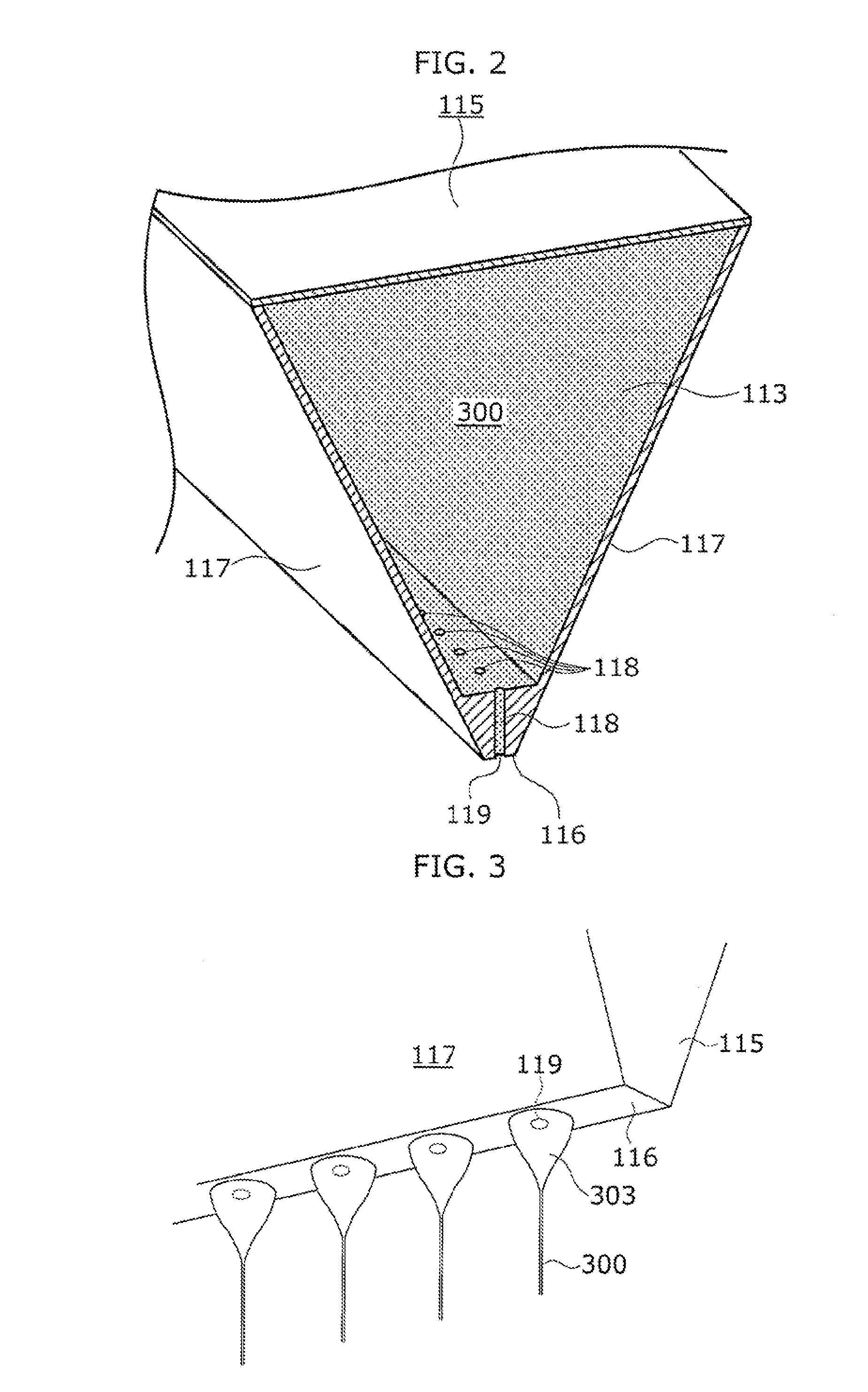
[0042]FIG. 2 is a perspective view illustrating a cutaway of the effusing body.

[0043]The effusing body 115 is a member for effusing the solution 300 into space by pressure of the solution 300 (and the gravity in some cas...


PUM

PropertyMeasurementUnit
Pressureaaaaaaaaaa
Diameteraaaaaaaaaa
Electric potential / voltageaaaaaaaaaa

Abstract

A nanofiber manufacturing apparatus (100) which produces nanofibers (301) by electrically stretching a solution (300) in space, includes: an effusing body (115) having effusing holes (118) for effusing the solution (300) into the space, a tip part (116) in which openings (119) at ends of the effusing holes (118) are one-dimensionally arranged at given intervals, and two side wall parts (117) provided extending from both sides of the tip part (116) so that the effusing holes (118) are located between the side wall parts (117) and distance between the side wall parts (117) increases with distance from the tip part (116); a charging electrode (121) disposed at a given distance from the effusing body (115); and a charging power supply (122) which applies a given voltage between the effusing body (115) and the charging electrode (121). The nanofiber manufacturing apparatus (100) keeps a high production rate per unit time and unit area and limits the impact of ionic wind while producing high and consistent quality of nanofibers.

Description

TECHNICAL FIELD[0001]The present invention relates to a nanofiber manufacturing apparatus which produces fibers having diameters of submicron order or nanometer order (referred to as nanofibers in this description) by electrostatic stretching, and a method of manufacturing nanofibers.BACKGROUND ART[0002]There is a known method of manufacturing filamentous (fibrous) substances containing a resin and having a submicron- or nanometer-scale diameter by making use of electrostatic stretching (electrospinning).[0003]The electrostatic stretching is a method of manufacturing nanofibers. In the method, a solution prepared by dispersing or dissolving a solute such as a resin in a solvent is effused (ejected) into space through a nozzle or the like, and the solution is charged and electrically stretched in flight so that nanofibers are produced.[0004]The following describes the electrostatic stretching more specifically. The solvent gradually evaporates from the charged solution while the solu...

Claims


Application Information

Patent Timeline
IPC IPC(8): D01D5/12B82Y40/00D01D5/04D04H1/728
CPCD01D5/0069D01D5/0076D01D5/0038B82Y40/00D01D5/00D01D13/00
Inventor ISHIKAWA, KAZUNORISUMIDA, HIROTOKUROKAWA, TAKAHIROMIYATA, MASANOBUMITSUSHIMA, TAKATOSHI
Owner PANASONIC INTELLECTUAL PROPERTY MANAGEMENT CO LTD
Why Eureka
Try Eureka