Light scattering sheet and method for producing the same

a technology of light scattering and light scattering sheets, applied in the direction of pretreatment surfaces, coatings, instruments, etc., can solve the problem of 25% inability to obtain, achieve excellent moire removal performance, reduce the thickness of liquid crystal display devices, and reduce the number of members

Inactive Publication Date: 2012-01-19
FUJIFILM CORP
View PDF6 Cites 12 Cited by
  • Summary
  • Abstract
  • Description
  • Claims
  • Application Information

AI Technical Summary

Benefits of technology

[0045]According to the light scattering sheet and the method for producing the same of the presently disclosed subject matter, a light scattering sheet having a transmitted image definition of 10% or more and less than 25% and excellent in moire-eliminating performance can be produced, because a phase-separated convexo-concave structure in which a plurality of domains have random shapes mainly having a string shape can be stably formed even if a coating layer is subjected to low speed drying at room temperature in the initial drying of the coating layer, in producing the light scattering sheet by a phase separation method.
[0046]Further, a reduction in the thickness of a liquid crystal display device can be achieved by reducing the number of members by making the light scattering sheet serve also as a protective sheet of a polarizing plate because triacetyl cellulose can be used as the transparent support.

Problems solved by technology

However, if the coating layer is subjected to low speed drying (for example, room temperature drying) in the initial drying in which a solvent concentration of a coating layer is high, like a method for producing a light scattering sheet by a conventional phase separation method, rotation convection will occur in the coating layer due to the difference in temperature between the upper layer and the lower layer of the coating layer or the difference in density between the upper layer and the lower layer.
A problem is that this produces a convective cell in the coating layer to form a regular or periodic phase-separated convexo-concave structure having a plurality of cellular domains, and a light scattering sheet with a low image definition having a transmitted image definition of 10% or more and less than 25% cannot be obtained.

Method used


Image

  • Light scattering sheet and method for producing the same
  • Light scattering sheet and method for producing the same
  • Light scattering sheet and method for producing the same

Examples


example 1

[0125]The features of the presently disclosed subject matter will now be more specifically described with reference to Examples, but the scope of the presently disclosed subject matter shall not be construed to be limited by specific examples described below.

[Test A]

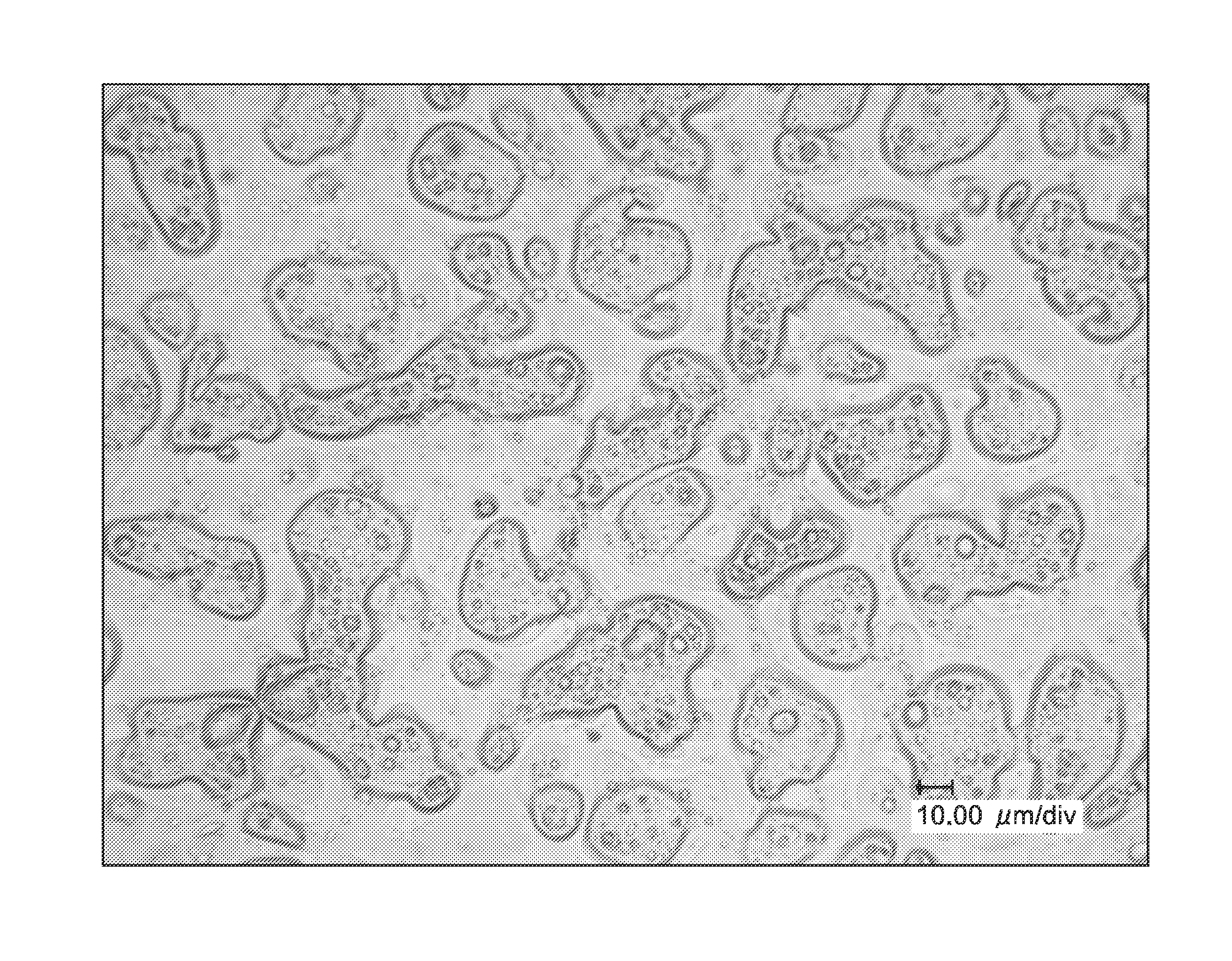
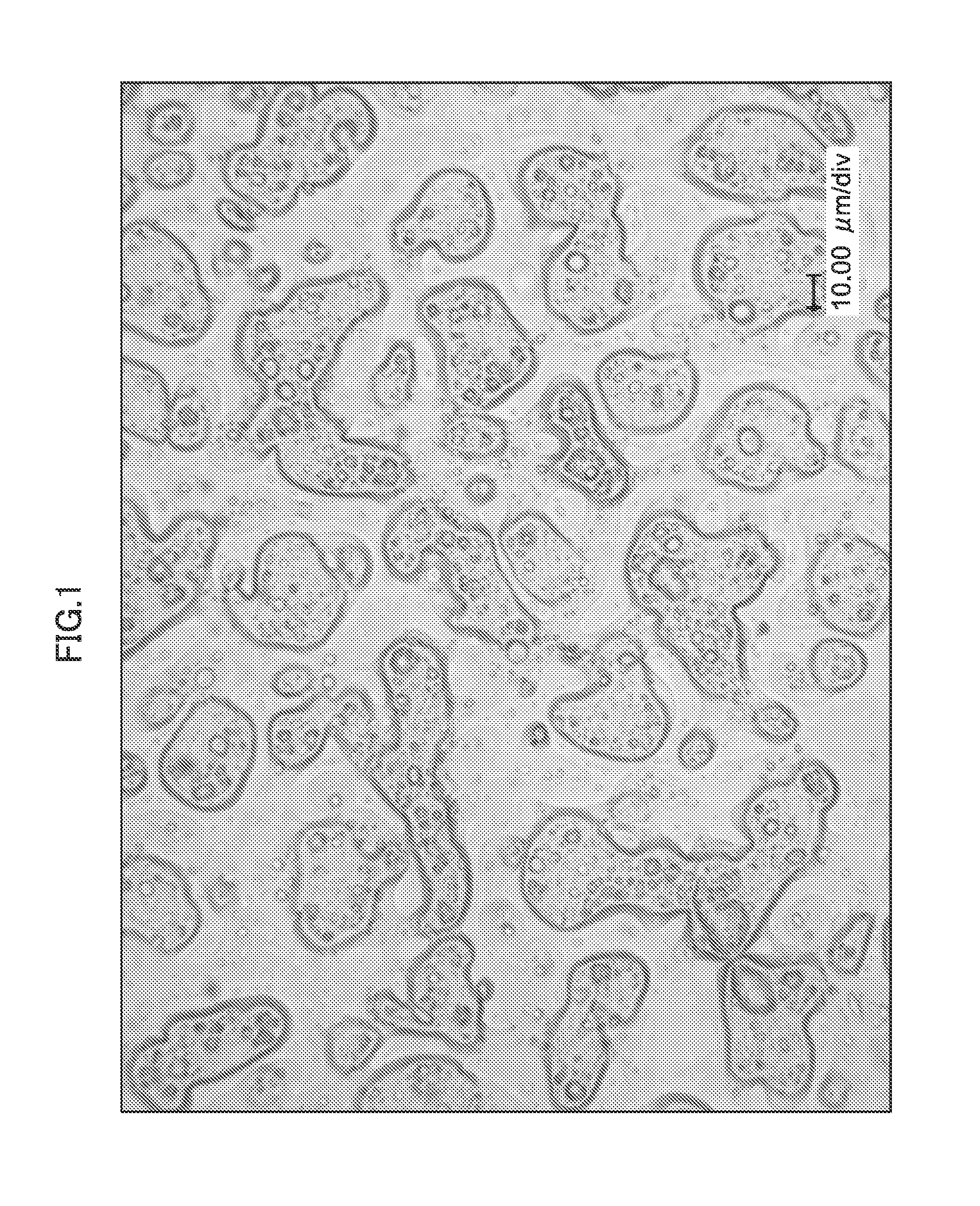
[0126]In Test A, a light scattering sheet was produced using five types of coating liquids for light scattering having the following composition, and then the transmitted image definition (%), the proportion (%) of the surface tilt angle in the range of 2.5 to 7.5°, and the degree of moire elimination were examined.

(Types of Coating Liquid for Light Scattering)

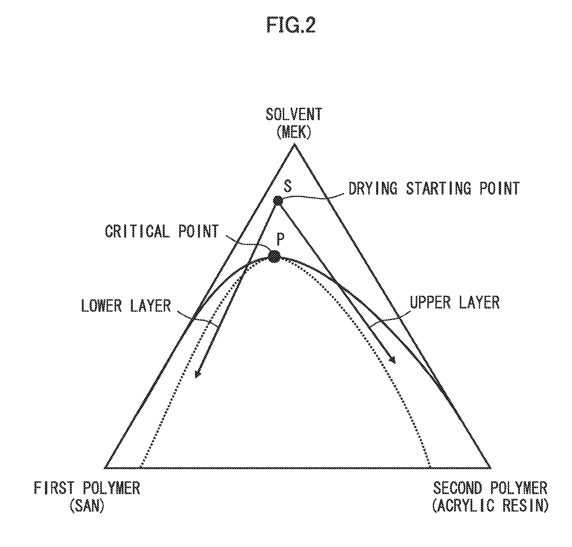
[0127]Five types of coating liquid for light scattering comprising the following resin materials and solvent were prepared.

Acrylic resin17.9 gStyrene-acrylonitrile copolymer (SAN) 2.4 gDipentaerythritol hexaacrylate18.3 gIRGACURE 184 (trademark) suppliedfrom BASF Schweiz AG 1.4 gMethyl ethyl ketone30.0 gMethoxy propyl acetate30.0 gAcrylic resin17.9 gCellulose aceta...


PUM

PropertyMeasurementUnit
boiling pointaaaaaaaaaa
widthaaaaaaaaaa

Abstract

A light scattering sheet includes: a transparent support; and a light scattering layer on the transparent support, the light scattering layer having a phase-separated convexo-concave structure formed by spinodal decomposition of a solution containing two or more resin materials capable of phase-separation from each other are dissolved in a solvent. In the light scattering layer, the phase-separated convexo-concave structure is formed into a sea-island structure of two or more resin materials including a styrene-acrylonitrile copolymer, and a plurality of domains constituting the islands have random shapes mainly having a string shape, and a transmitted image definition measured according to JTS K 7374 using an optical comb having a width of 2.0 mm is 10% or more and less than 25%.

Description

BACKGROUND OF THE INVENTION[0001]1. Field of the Invention[0002]The presently disclosed subject matter relates to a light scattering sheet and a method for producing the same, particularly to a light scattering sheet used for a liquid crystal display device and a method for producing the same.[0003]2. Description of the Related Art[0004]In recent years, a liquid crystal display has been widely used because it is thin and light. A cold-cathode tube (CCFL: Cold Cathode Fluorescent Lamp) and an LED (Light Emitting Diode) are generally used as a light source of a back light unit which constitutes a light source of a liquid crystal display. These light sources are a linear light source or a point light source and have luminance distribution. A member for scattering light such as a light scattering (or light diffusion) sheet is used to convert these light sources into a surface light source.[0005]Further, a prism sheet, a reflection-type polarizing film, and the like are used to condense ...

Claims


Application Information

Patent Timeline
Patent Type & Authority Applications(United States)
IPC IPC(8): G02B5/02B05D3/00B05D5/06
CPCG02B5/0221G02B5/0278G02B5/0268G02B5/02G02F1/1335C08J5/18
Inventor OKI, KAZUHIRO
Owner FUJIFILM CORP
Why Eureka
Try Eureka