Suspension substrate, suspension, head suspension, hard disk drive, method for manufacturing suspension substrate, and method for testing continuity of suspension

a manufacturing method and suspension technology, applied in the direction of conductive pattern formation, instruments, record information storage, etc., can solve the problems of piezoelectric element not being connected with the wiring section, conductive adhesive injected into the liquid stopper may not adequately reach the wiring section, etc., to achieve secure electrical connection between the suspension substrate and the actuator element.

Inactive Publication Date: 2012-01-19
DAI NIPPON PRINTING CO LTD
View PDF11 Cites 16 Cited by
  • Summary
  • Abstract
  • Description
  • Claims
  • Application Information

AI Technical Summary

Benefits of technology

[0028]According to the present invention, the wiring connection section of the wiring layer can be electrically connected with the metallic support layer via the conductive connection section. Further, the metallic support layer can be electrically connected with the actuator element via the conducti...

Problems solved by technology

However, in the case of joining the terminal portion of the piezoelectric element to the suspension substrate by using the conductive adhesive, there is a risk that the conductive adhesive inject...

Method used


Image

  • Suspension substrate, suspension, head suspension, hard disk drive, method for manufacturing suspension substrate, and method for testing continuity of suspension
  • Suspension substrate, suspension, head suspension, hard disk drive, method for manufacturing suspension substrate, and method for testing continuity of suspension
  • Suspension substrate, suspension, head suspension, hard disk drive, method for manufacturing suspension substrate, and method for testing continuity of suspension

Examples


first embodiment

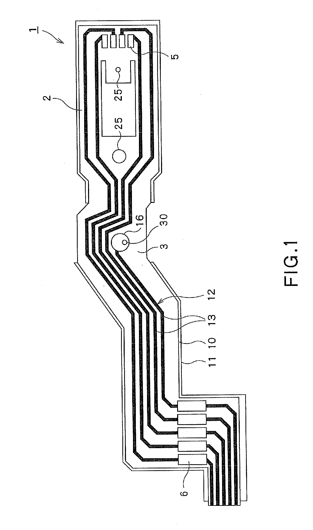
[0048]Now, referring to FIGS. 1 through 9, the suspension substrate, suspension, head suspension and hard disk drive, respectively related to the first embodiment of the present invention, will be described.

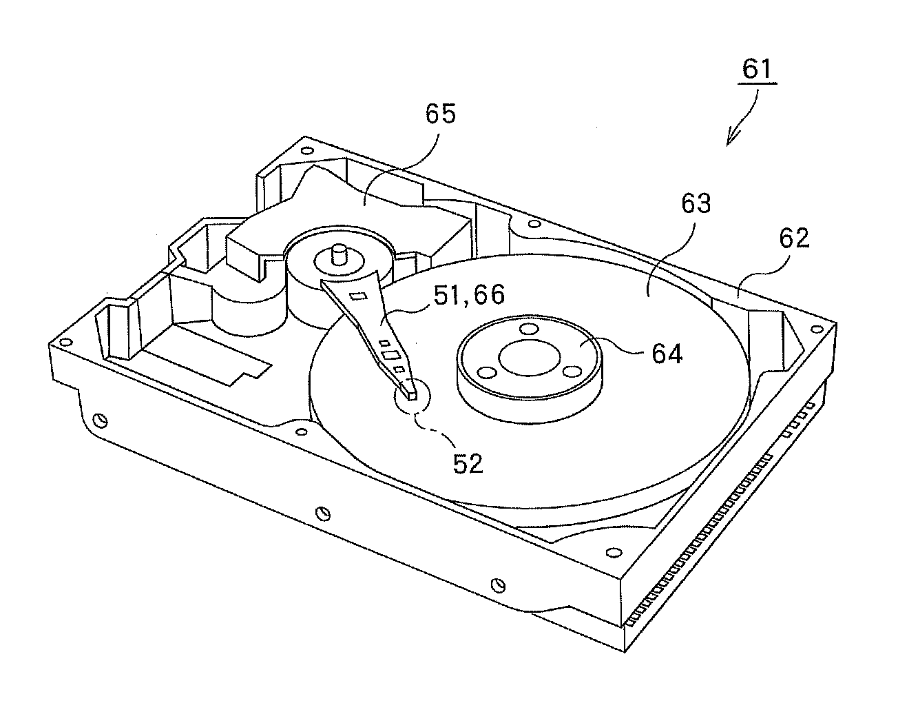
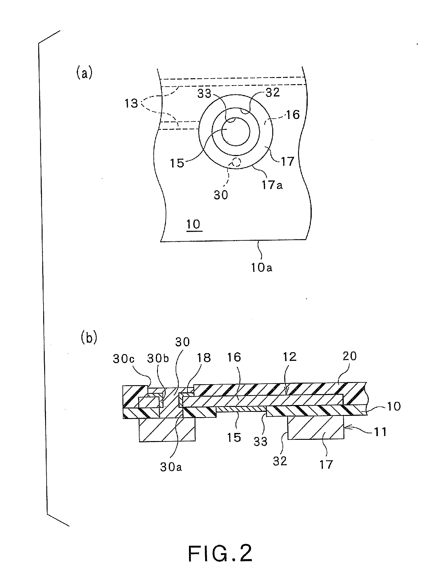
[0049]As shown in FIG. 1, the suspension substrate 1 includes a substrate main body region 2 having the wirings 13 that respectively extend along this substrate main body region 2 and will be described later, and the connection structure region 3 that can be connected with the piezoelectric element (or actuator element (see FIG. 3)) 44 that will be described later. The substrate main body region 2 includes a head terminal 5 provided to be connected with the slider 52 (see FIG. 7) that will be described later, and an external equipment connection terminal 6 provided to be connected with external equipment (not shown). In this case, the wirings 13 are respectively provided to extend between the head terminal 5 and the external equipment connection terminal 6, in order to connect th...

second embodiment

[0097]Now, referring to FIG. 12, the suspension substrate, suspension, head suspension, hard disk drive, method for manufacturing the suspension substrate and method for testing the continuity of the suspension, respectively related to the second embodiment of the present invention, will be described.

[0098]As shown FIG. 12, the second embodiment features that the metallic-support-layer injection hole and insulating-layer injection hole are not respectively provided. However, except for this feature, the other construction of this second embodiment is substantially the same as the first embodiment shown in FIGS. 1 through 9. It is noted that like parts in the first embodiment shown in FIGS. 1 through 9 are respectively designated by like reference numerals in FIG. 12, and further explanation on such parts will be omitted below.

[0099]Namely, as shown in FIG. 12, the metallic support layer includes a disk portion 70 provided in the connection structure region 3 and formed into a disk-l...

third embodiment

[0103]Next, referring to FIGS. 13 and 14, the suspension substrate, suspension, head suspension, hard disk drive, method for manufacturing the suspension substrate and method for testing the continuity of the suspension, respectively related to the third embodiment of the present invention, will be described.

[0104]As shown in FIGS. 13 and 14, the third embodiment features that the outer periphery of the frame portion of the metallic support layer is positioned outside relative to the outer periphery of the insulating layer and the outer periphery of the protective layer, and that a through hole for exposing the wiring connection section of the wiring layer is provided in the protective layer, with the gold plating being provided to the exposed portion of the wiring connection section in the through hole. However, except for this key point, the other construction of this third embodiment is substantially the same as the first embodiment shown in FIGS. 1 through 9. It is noted that li...


PUM

PropertyMeasurementUnit
Electrical conductoraaaaaaaaaa
Metallic bondaaaaaaaaaa

Abstract

A suspension substrate according the present invention includes: an insulating layer; a metallic support layer provided on the actuator element's side of the insulating layer. A wiring layer is provided on the other side of the insulating layer. This wiring layer includes a plurality of wirings and a wiring connection section that can be electrically connected with the actuator element via a conductive adhesive. A conductive connection section extending through the insulating layer and configured to connecting the metallic support layer with the wiring connection section of the wiring layer is provided in the connection structure region.

Description

CROSS REFERENCE TO RELATED APPLICATIONS[0001]This application is based on the prior Japanese Patent Application No. 2010-160933 filed on Jul. 15, 2010, the entire contents of which are incorporated herein by reference.FIELD OF THE INVENTION[0002]The present invention relates to a suspension substrate, a suspension, a head suspension, a hard disk drive, a method for manufacturing the suspension substrate and a method for testing continuity of the suspension. In particular, this invention relates to the suspension substrate, suspension, head suspension, hard disk drive, method for manufacturing the suspension substrate and method for testing the continuity of the suspension, respectively adapted for enhancing reliability of electrical connection relative to an actuator element used.BACKGROUND ART[0003]Generally, the hard disk drive (HDD) includes the suspension substrate on which a magnetic head slider mounted. In this case, the magnetic head slider is provided for writing and reading...

Claims


Application Information

Patent Timeline
IPC IPC(8): G11B21/24H05K3/10G01R31/28H05K1/11H05K1/09
CPCH05K3/0061G11B5/4833H05K1/056Y10T29/49004G11B5/486Y10T29/49155H05K3/4053
Inventor OHNUKI, MASAOMIURA, YOICHI
Owner DAI NIPPON PRINTING CO LTD
Why Eureka
Try Eureka