Disc pump

a disc pump and pump body technology, applied in the field of pumps, can solve the problems of affecting the performance of the pump, the the failure of the pump, etc., and achieve the effect of improving the pump performance, reducing the long-wear and high-reliability attributes

Inactive Publication Date: 2012-01-19
RIG POWER
View PDF4 Cites 19 Cited by
  • Summary
  • Abstract
  • Description
  • Claims
  • Application Information

AI Technical Summary

Benefits of technology

[0018]The present invention utilizes a unique design for the discs that makes the pump particularly suited handling multiphase fluids with solids, liquids, and gases. Such fluids are typical of oil and gas wells, geothermal energy produ

Problems solved by technology

The vanes, buckets, or the like, of traditional pumps wear and lose effectiveness due to normal friction and/or impingement with particles such as sand or other abrasives.
Typical vaned centrifugal pumps often require precise gaps between the impellors and the pump housing.
When the impellor vanes or blades of such a pump begin to wear, the pump becomes less efficient and may either pump less fluid or produce less outlet pressure, depending upon the application.
Cavitation is another problem that sometimes arises with traditional axial, bladed, centrifugal, and mixed-flow pumps Cavitation describes a vacuum-like condition in the pump which can occur when liquid in the low-pressure area of the pump vaporizes.
Cavitation can create a shock wave powerful enough to damage a pump, other equipment, or connections to the pump or other equipment.
Such a fluid can quickly wear down the impellor blades in a typical centrifugal pump, while the same fluid may cause little or no damage to a disc pump.
Other problems related to more traditional pumps include vapor lock problems, and pump efficiencies being limited by affinity laws.
The flow to head ratio is often restricted

Method used


Image

  • Disc pump
  • Disc pump
  • Disc pump

Examples


Embodiment Construction

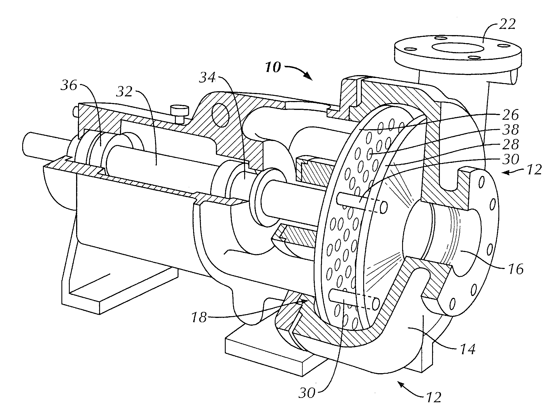
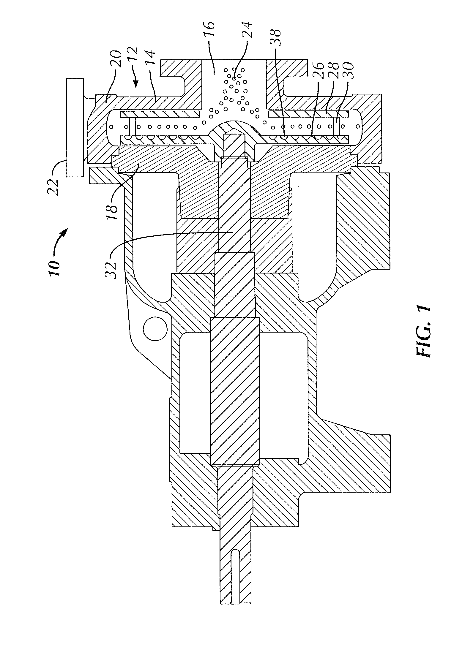
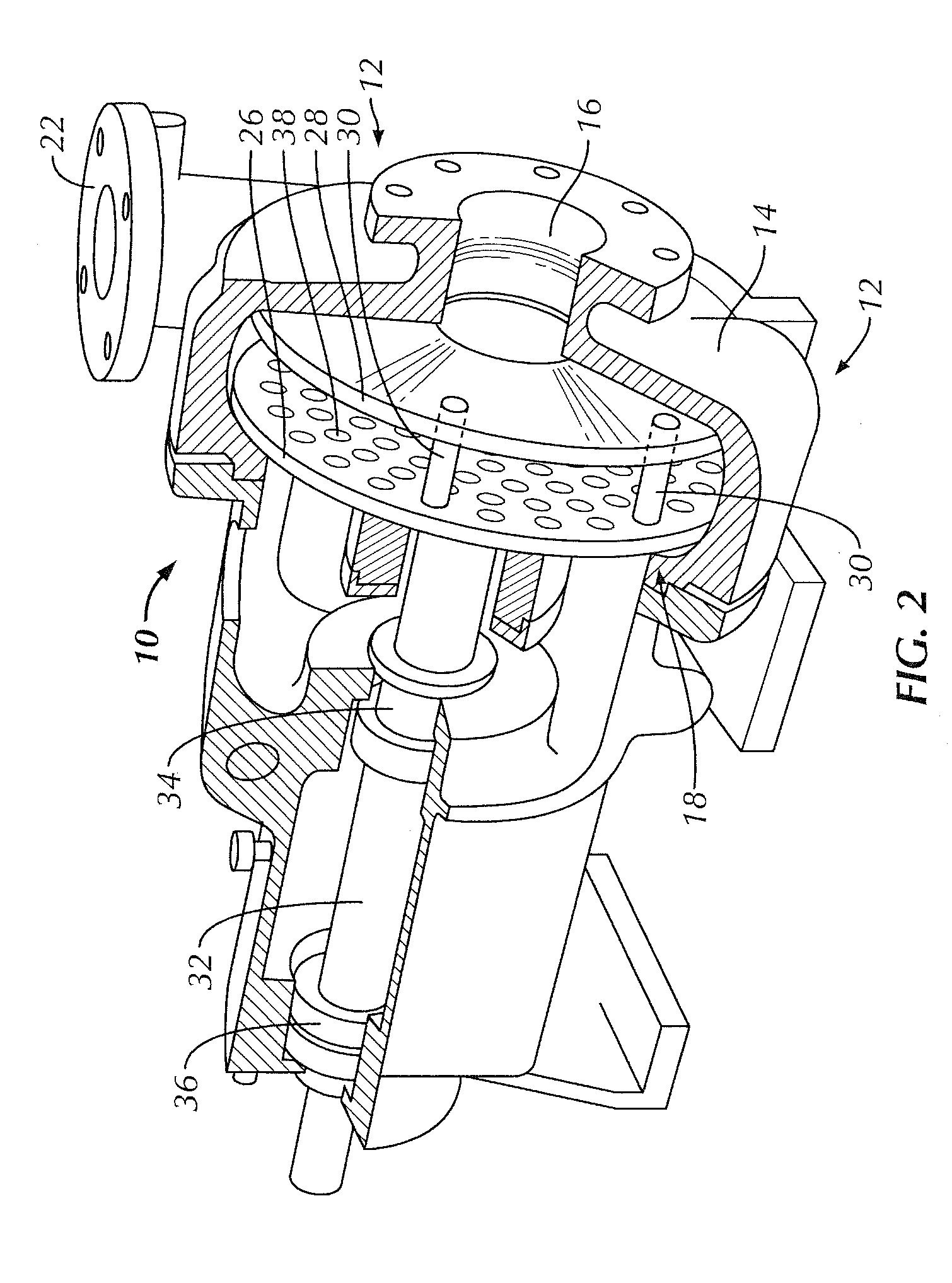
[0029]A cross section of a typical boundary layer or disc pump 10 is shown in FIG. 1. The portion of interest for this description is seen on the right end of the drawing. A pump housing 12 is formed by a front wall 14, a back wall 18, and a peripheral wall 20. These three walls may be distinct pieces or two or more of the walls may be a single part. The three walls are defined in this way based on the physical configuration of the pump housing. This definitional choice is not meant to limit the type of housing in any way. It is for convenience only.

[0030]The pump 10 has a inlet 16 located near the center of the front wall 14. The inlet 16 is aligned with the longitudinal axis of the pump drive shaft 32. The inlet 16, therefore, can be described as a central, coaxial inlet. The inlet 16 can take various forms. It can supply feed flow from one side of the housing 12 or from both sides of the housing. A design showing dual inlet flow from both sides of the housing is disclosed in U.S....


PUM


Abstract

A pump is disclosed having one or more rotating discs within a housing. The discs have a plurality of relatively small surface perturbations covering at least half of one side of their surface. The perturbations may be recessed or raised. In operation, a boundary layer is formed near the surface of the rotating discs. The fluid within the pump flows in a circular and outward direction, thus moving fluid from a central coaxial inlet to an outlet located at the peripheral wall of the housing. The surface perturbations produce turbulence within the boundary layer during operation. The pump is suitable for pumping liquids with entrained gases, liquids with entrained solids, liquids with both gases and solids, and thick liquids.

Description

FIELD OF THE INVENTION[0001]The invention relates to a pump, and more particularly to a disc pump wherein the disc or discs have a plurality of surface perturbations covering at least half the surface area of one side of the disc or discs.BACKGROUND OF THE INVENTION[0002]Boundary layer or bladeless turbines, pumps, and other related turbo-machinery have been known for 100 years or more. Nikola Tesla obtain a patent (U.S. Pat. No. 1,061,142) for such a device in 1913. The Tesla patent disclosed a multiple-disc pump that utilized rotating flat discs with no blades, vanes, or propellers. Such pumps have been referred to as disc pumps, boundary layer pumps, or bladeless pumps.[0003]In related U.S. Pat. No. 1,061,206, Tesla disclosed a fluid-driven boundary layer or bladeless turbine which may be utilized as a prime mover in various applications. The Tesla bladeless turbine, when used as the driving force for a hydro-electric generator, could transform the kinetic energy of a flowing flu...

Claims


Application Information

Patent Timeline
IPC IPC(8): F01D1/36F04D5/00
CPCF04D5/001
Inventor GILLIAM, CHARLES DAVID
Owner RIG POWER
Why Eureka
Try Eureka