Endoscope beam source apparatus and endoscope system

Inactive Publication Date: 2012-01-19
FUJIFILM CORP
View PDF3 Cites 29 Cited by
  • Summary
  • Abstract
  • Description
  • Claims
  • Application Information

AI Technical Summary

Benefits of technology

[0023]According to the endoscope beam source apparatus of the invention and an endoscope system including such apparatus, since the radiation beam is controlled by integrating the combinations of three or more kinds of modulation control, there can be easily obtained a broad

Problems solved by technology

Realization of such broad beam quantity dynamic range is difficult simply by controlling the amplitude of a current to be applied to the beam source.
However, in any one of the pulse number control, pulse width control and pulse amplitude control, a sufficiently large beam quantity dynamic range cannot be obtained when only one of them is applied.
Therefore, an operation to adjust the radiation beam quantity to a desired value is very difficult.
Further, in the case that the beam quantity is controlled using the pulse number control, pulse width control and p

Method used


Image

  • Endoscope beam source apparatus and endoscope system
  • Endoscope beam source apparatus and endoscope system
  • Endoscope beam source apparatus and endoscope system

Examples


Embodiment Construction

[0038]Now, description will be given below specifically of an embodiment according to the invention with reference to the accompanying drawings.

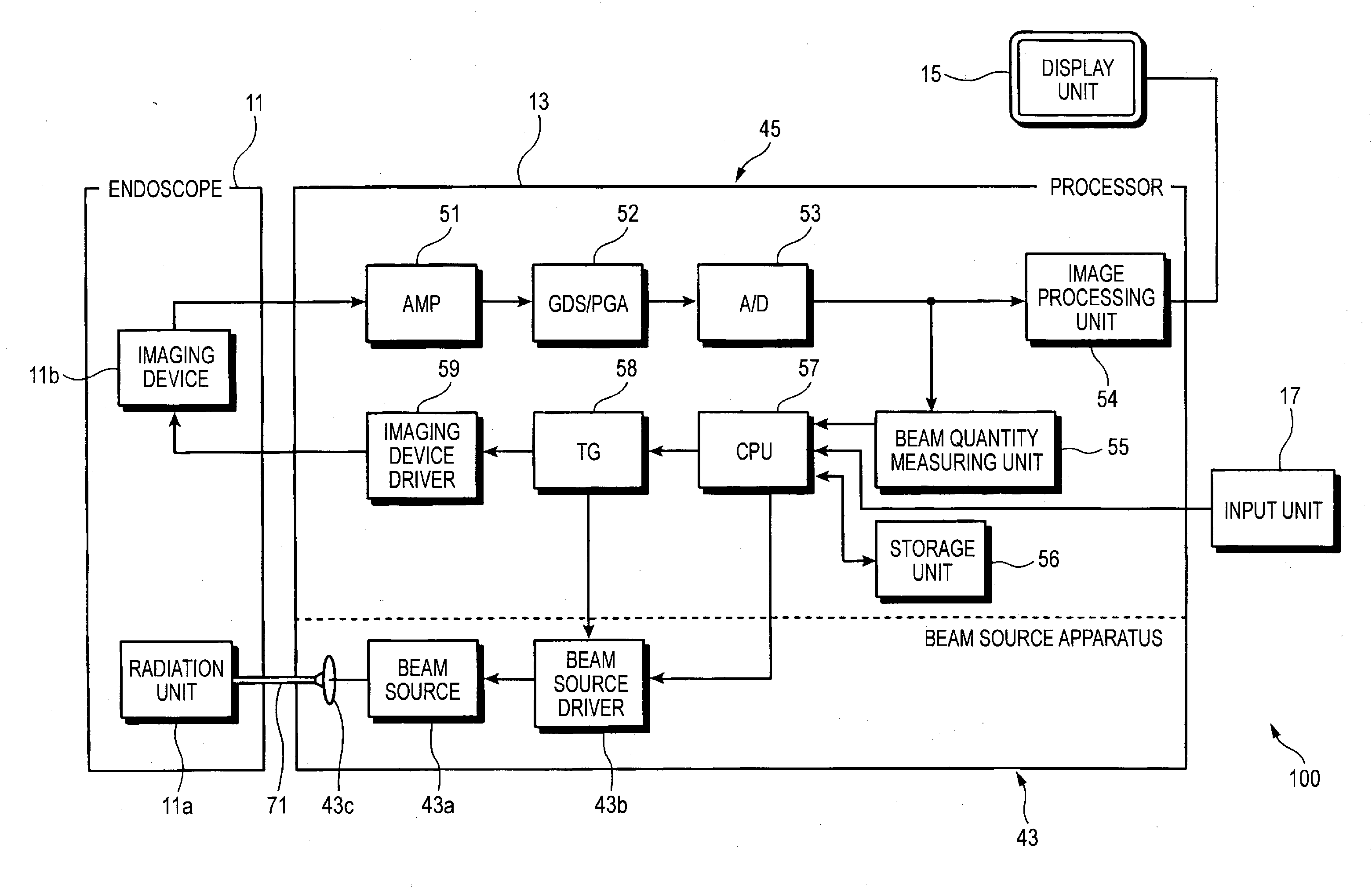
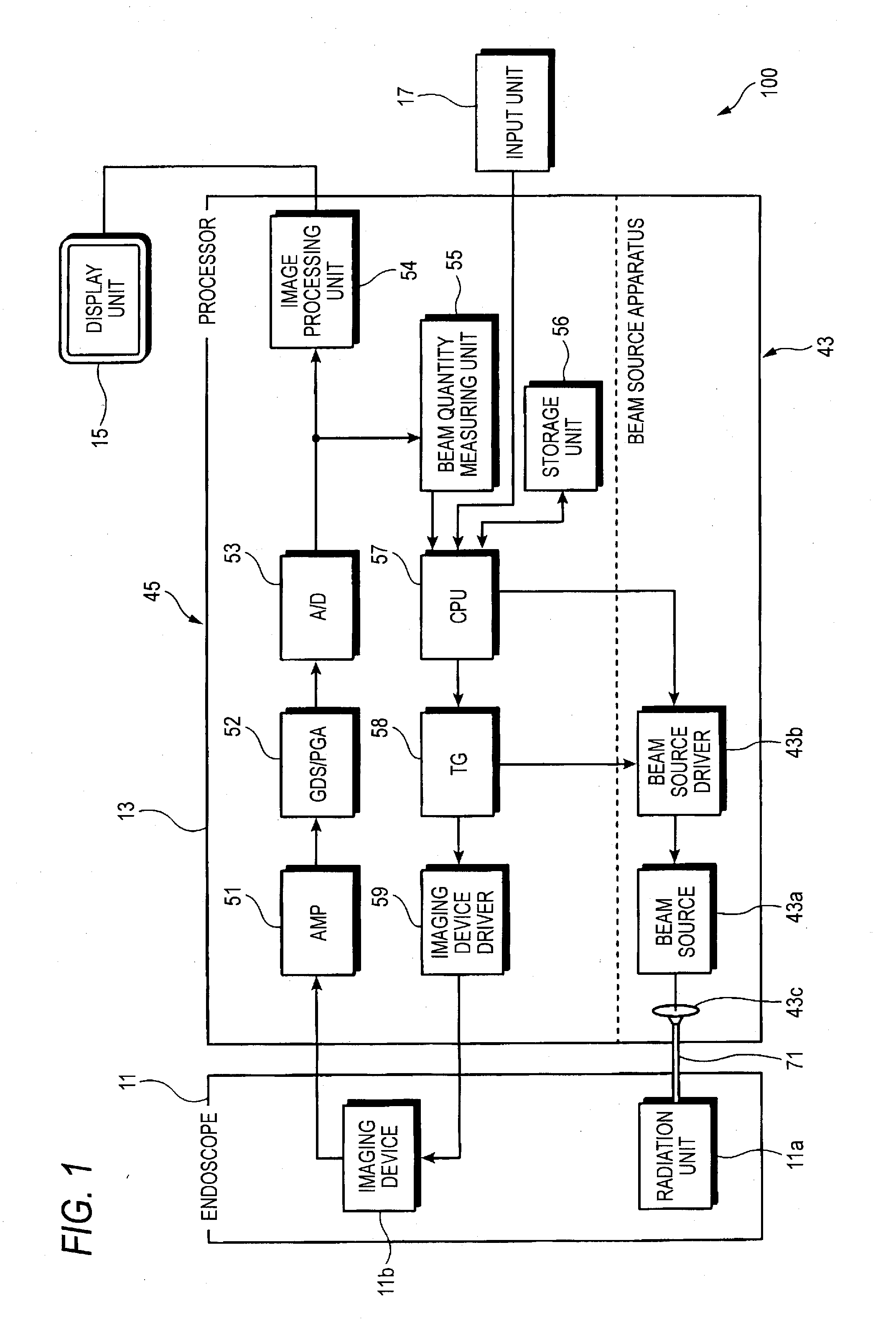
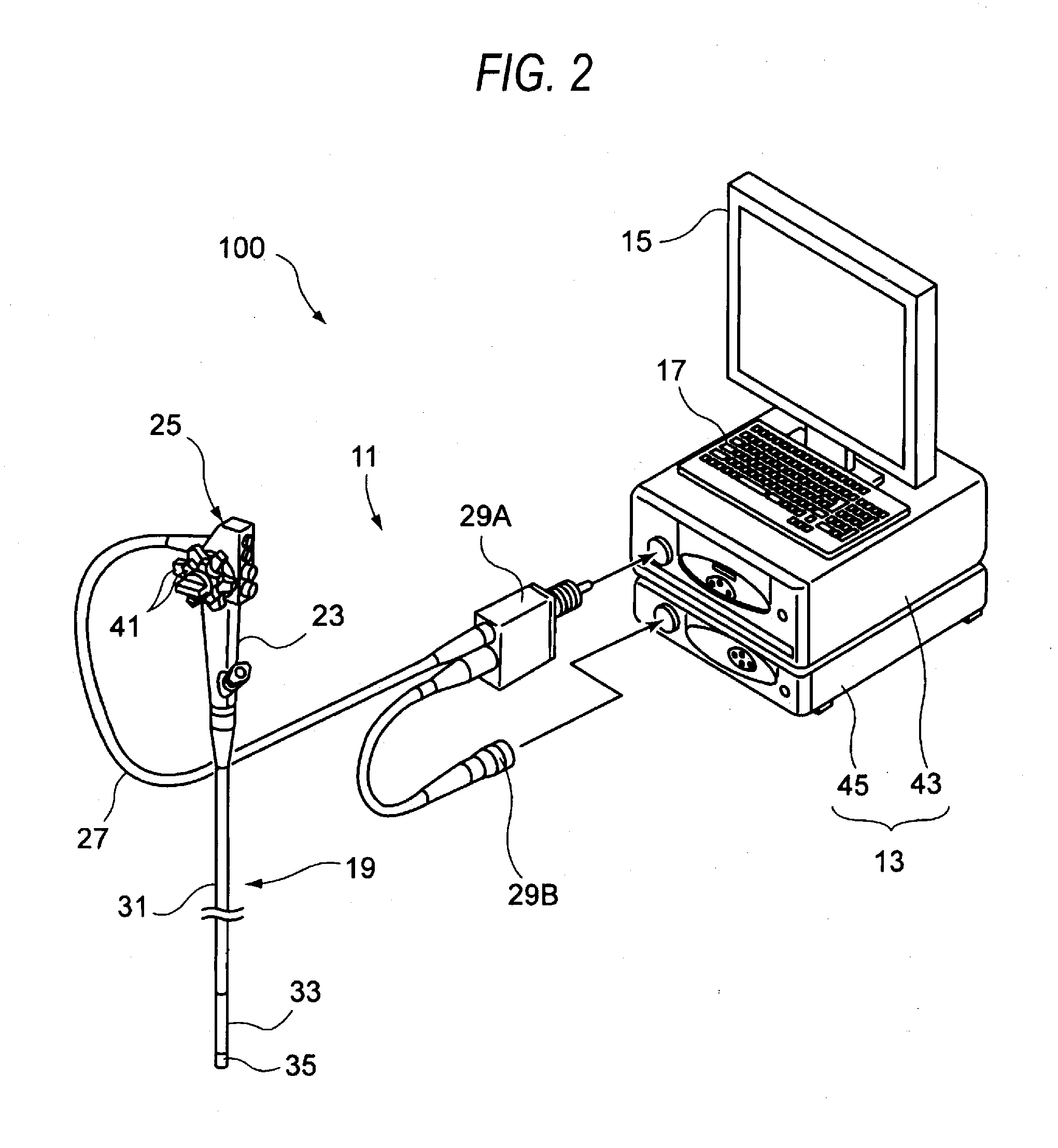
[0039]An example of the structure of the main portions of the whole endoscope system according to the present embodiment is shown in FIG. 1. Also, the appearance of the endoscope system shown in FIG. 1 is shown in FIG. 2.

[0040]As shown in FIGS. 1 and 2, an endoscope system 100 includes an endoscope 11, a control unit 13 as an external control unit to which the endoscope 11 can be connected, and a display unit 15 connected to the control unit 13 for displaying image information. And, an input unit 17 is connected to the control unit 13 for accepting an input operation.

[0041]The endoscope 11 is an electronic endoscope which, as shown in FIG. 1, includes a radiation unit 11a (a radiation optical system) and an imaging device 11b (an imaging optical system). The radiation unit 11a emits a radiation beam from the leading end of an endoscope inser...


PUM


Abstract

The endoscope beam source apparatus includes a beam source for emitting a radiation beam to be supplied to the endoscope, and a beam source control unit for controlling the emission beam intensity of the beam source according to a beam quantity specified value input therein. The beam source control unit specifies the emission beam intensity corresponding to the beam quantity specified value based on at least three of control amounts. The control amounts include a control amount corresponding to pulse number modulation (PNM) control for changing lighting time of the beam source, a control amount corresponding to pulse width modulation (PWM) control for changing a plus width which indicates the lighting or lighting-out time within a control cycle, a control amount corresponding to pulse amplitude modulation (PAM) control for changing the lighting intensity, and a control amount corresponding to pulse density modulation (PDM) control for changing a lighting interval.

Description

CROSS-REFERENCE TO RELATED APPLICATIONS[0001]This application claims the benefit of Japanese Patent Application No. 2010-160682, filed on Jul. 15, 2010, the entire contents of which are hereby incorporated by reference, the same as if set forth at length.BACKGROUND OF THE INVENTION[0002]1. Technical Field[0003]The present invention relates to an endoscope beam source apparatus and an endoscope system including such apparatus.[0004]2. Description of Related Art[0005]Generally, to observe tissue within a body cavity, there is used an endoscope system. The endoscope system is a system which radiates, as a radiation beam, a white beam onto a portion to be observed within the body cavity, picks up a beam image due to a reflection beam from the portion to be observed using a predetermined imaging device which is capable of imaging a two-dimensional image, and displays the thus obtained two-dimensional image on a monitor screen. A technology for controlling the radiation beam of such endos...

Claims


Application Information

Patent Timeline
IPC IPC(8): A61B1/06
CPCA61B1/045A61B1/0669A61B1/0653A61B1/0655H04N23/555H04N23/56H04N25/531
Inventor SETO, YASUHIROMURAKAMI, HIROSHI
Owner FUJIFILM CORP
Why Eureka
Try Eureka