Method And Apparatus For Controlling The Flow Of Fluids From A Well Below The Surface Of The Water

Inactive Publication Date: 2012-01-26
KOTEFSKI STOJAN +2
View PDF8 Cites 11 Cited by
  • Summary
  • Abstract
  • Description
  • Claims
  • Application Information

AI Technical Summary

Benefits of technology

[0036](c) lowering the fluid control device into the open casing until the fluid control devi

Problems solved by technology

The smaller diameter allows for a smaller area upon which the fluid flow can exer

Method used


Image

  • Method And Apparatus For Controlling The Flow Of Fluids From A Well Below The Surface Of The Water
  • Method And Apparatus For Controlling The Flow Of Fluids From A Well Below The Surface Of The Water
  • Method And Apparatus For Controlling The Flow Of Fluids From A Well Below The Surface Of The Water

Examples


Embodiment Construction

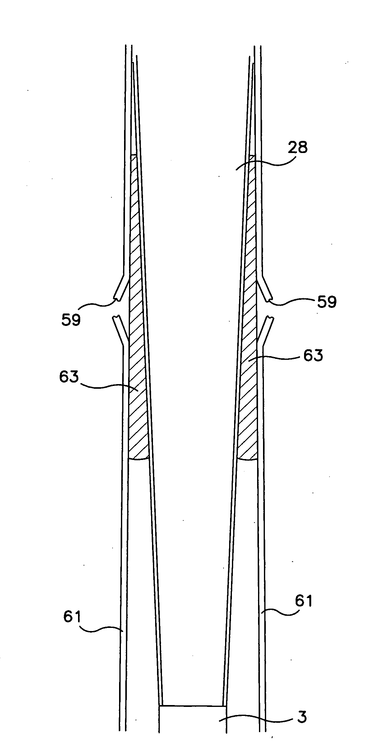
[0058]As illustrated in FIGS. 4 and 8(a), the fluid control device 10 of the present invention is generally comprised of three members, i.e., elongated member 31, tapered portion 28 (which may be coated with a soft material such that the diameter of the tapered portion is greater than the inside diameter of the outflowing pipe) and top portion 25. In particular, the elongated member 31 having a tip 33 at one end thereof, is smallest in diameter, and is disposed at one end of the device 10 so as to be the first element of the device 10 to be inserted into a well head casing 5. The elongated member 31 is in communication with, or formed integral with, a tapered portion 28 at juncture 35, the juncture 35 being at an end opposite the tip 31. The elongated member 28 is in communication with or formed integral with top portion 25. Top portion 25 preferably has a shoulder 26 formed therein, the shoulder 26 having a diameter equal or greater that the outside diameter of the well head casing...


PUM


Abstract

An apparatus and method is provided for controlling and/or halting the uncontrolled flow of petroleum and/or natural gas from an open well head on the sea floor in which the well head is in communication with a subterranean formation. The method includes lowering a fluid control device from a drilling ship to an alignment means positioned above an open well casing through which the petroleum and/or natural gas is flowing in an uncontrolled manner, then lowering the fluid control device through and/or adjacent to the alignment means and into the open well casing until a lower section of a fluid control device enters the open well casing. The fluid control device includes an elongated member at its tip, having a diameter smaller than the inside diameter of the well head casing. A tapered section is in connection with the elongated section, the tapered section, or another section in connection with the tapered section, having a maximum diameter equal to or greater than the inside diameter of the well casing, and an end section in communication with the tapered section having a diameter greater than or equal to the outside diameter of the well head casing. The fluid control device can have a mass sufficiently great to overcome any upward forces created by flowing petroleum and/or natural gas, resulting in sufficient downward movement of the fluid control device and contact with the open well casing to seal same. Alternatively, a drilling rig in connection with the fluid control device can exert sufficient downward pressure thereon so as to overcome the pressure of the flowing petroleum, gas, etc., thereby creating a seal between the fluid control device and the well head.

Description

BACKGROUND OF THE INVENTION[0001]1. Field of the Invention[0002]The present invention relates in general to a method and apparatus for controlling the flow of fluids from a subsurface well, i.e., a well positioned below the surface of the water. More particularly, the present invention provides a method and apparatus for controlling and plugging an undersea oil and / or gas well.[0003]2. Description of the Related Art[0004]In the production of fluids such as petroleum and / or natural gas from subterranean formations, accidents can occur due to human and equipment malfunctions or the like, thereby occasionally producing a condition known as blowout. In such instances, the flow of fluids from a subterranean formation under substantial pressure is unrestricted, with the fluids flowing to the surface, i.e., a sea floor or a land surface. In such instances, it is desirable that a method and apparatus be available for controlling or stopping the flow of such petroleum and / or natural gas beca...

Claims


Application Information

Patent Timeline
IPC IPC(8): E21B33/12E21B19/00
CPCE21B43/0122
Inventor KOTEFSKI, STOJANKOTEVSKI, NIKOLASHIN, DAE
Owner KOTEFSKI STOJAN
Why Eureka
Try Eureka