Wireless energy transfer apparatus and method for manufacturing the same

Inactive Publication Date: 2012-01-26
ELECTRONICS & TELECOMM RES INST
View PDF11 Cites 39 Cited by
  • Summary
  • Abstract
  • Description
  • Claims
  • Application Information

AI Technical Summary

Benefits of technology

[0010]An embodiment of the present invention is directed to a wireless power transf

Problems solved by technology

Although such a method is widely used in a wireless communication scheme, it is not an efficient energy transfer method.
In the method developed by MIT, however, the size and the resonant frequency have values which are

Method used


Image

  • Wireless energy transfer apparatus and method for manufacturing the same
  • Wireless energy transfer apparatus and method for manufacturing the same
  • Wireless energy transfer apparatus and method for manufacturing the same

Examples


Embodiment Construction

[0031]Exemplary embodiments of the present invention provide a resonant structure, and the material, structure, and manufacturing method thereof will be described.

[0032]Exemplary embodiments of the present invention will be described below in more detail with reference to the accompanying drawings. The present invention may, however, be embodied in different forms and should not be constructed as limited to the embodiments set forth herein. Rather, these embodiments are provided so that this disclosure will be thorough and complete, and will fully convey the scope of the present invention to those skilled in the art.

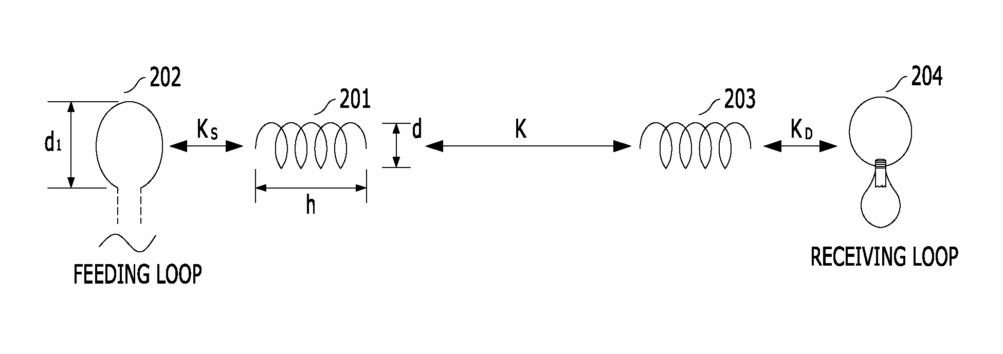
[0033]Furthermore, the embodiments of the present invention relate to the structure of a resonant element for wireless power transfer using magnetic resonance, and specifically, to an apparatus and method for miniaturization. For this structure, the resonant element in accordance with the embodiments of the present invention has a structure for miniaturization through a ...


PUM

PropertyMeasurementUnit
Frequencyaaaaaaaaaa
Frequencyaaaaaaaaaa
Thicknessaaaaaaaaaa

Abstract

A wireless power transfer apparatus includes: a transmitting coil into which a current having a predetermined frequency is introduced; a receiving coil configured to supply a current induced by electromagnetic induction to a load; and a transmission-side resonant coil and a reception-side resonant coil positioned between the transmitting coil and the receiving coil, configured to provide the current flowing in the transmitting coil to the receiving coil through electromagnetic induction, and spaced a predetermined distance from each other. Each of the resonant coils has a spiral structure.

Description

CROSS-REFERENCE TO RELATED APPLICATIONS[0001]The present application claims priority of Korean Patent Application No. 10-2010-0071249, filed on Jul. 23, 2010, which is incorporated herein by reference in its entirety.BACKGROUND OF THE INVENTION[0002]1. Field of the Invention[0003]Exemplary embodiments of the present invention relate to a wireless power transfer apparatus; and, more particularly, to a wireless power transfer apparatus using magnetic resonance, a method for manufacturing a resonant coil thereof, and a method for tuning a resonant frequency.[0004]2. Description of Related Art[0005]Energy is a term to express the ability that a physical system has to do work on the other physical systems, and a physical terminology of heat, electricity, power or the like. Representative examples of such energy may include electrical energy, firepower energy, hydraulic energy, thermal energy and so on. The most basic method for transferring electrical energy among the energies is to tran...

Claims


Application Information

Patent Timeline
IPC IPC(8): H02J17/00H01F7/06
CPCH01F38/14Y10T29/49071H02J17/00H02J5/005H02J50/12H02J50/70
Inventor CHO, IN-KUIYUN, JE-HOONMOON, JUNG-ICKKIM, SEONG-MIN
Owner ELECTRONICS & TELECOMM RES INST
Why Eureka
Try Eureka