Coupling structures for microwave filters

Inactive Publication Date: 2012-01-26
TRIASX PTY LTD
View PDF1 Cites 5 Cited by
  • Summary
  • Abstract
  • Description
  • Claims
  • Application Information

AI Technical Summary

Benefits of technology

[0007]It is an object of the invention to overcome or alleviate one or more of the a

Problems solved by technology

This is especially the case between the WCDMA and GSM900 bands which are located adjacent each other and often causing substantial interference.
Losses in radio communications systems, such as insertion loss in filters, also contribute to the reduction in call quality.
Generally larger amplifiers are used to offset this loss howe

Method used


Image

  • Coupling structures for microwave filters
  • Coupling structures for microwave filters
  • Coupling structures for microwave filters

Examples


Embodiment Construction

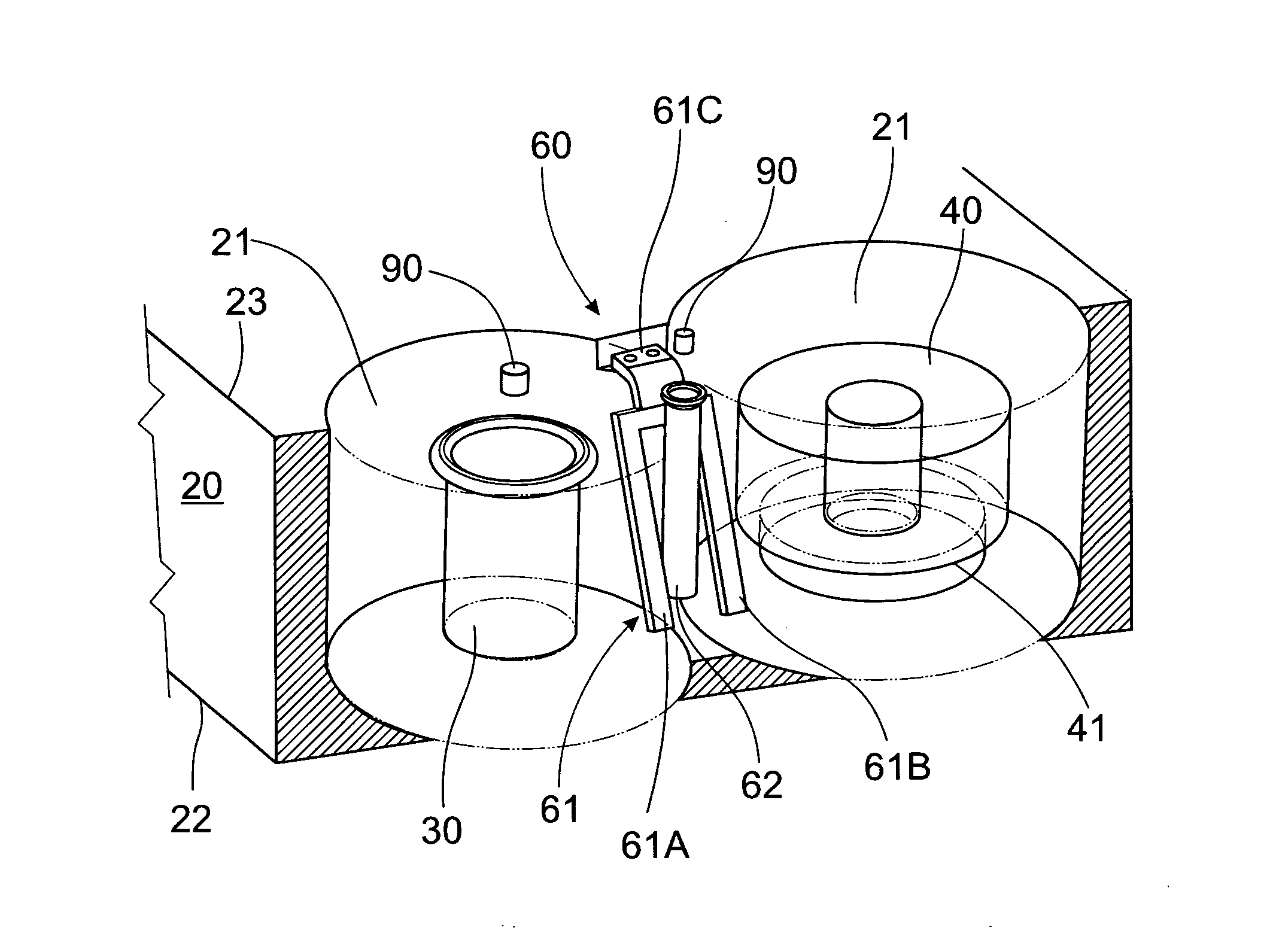
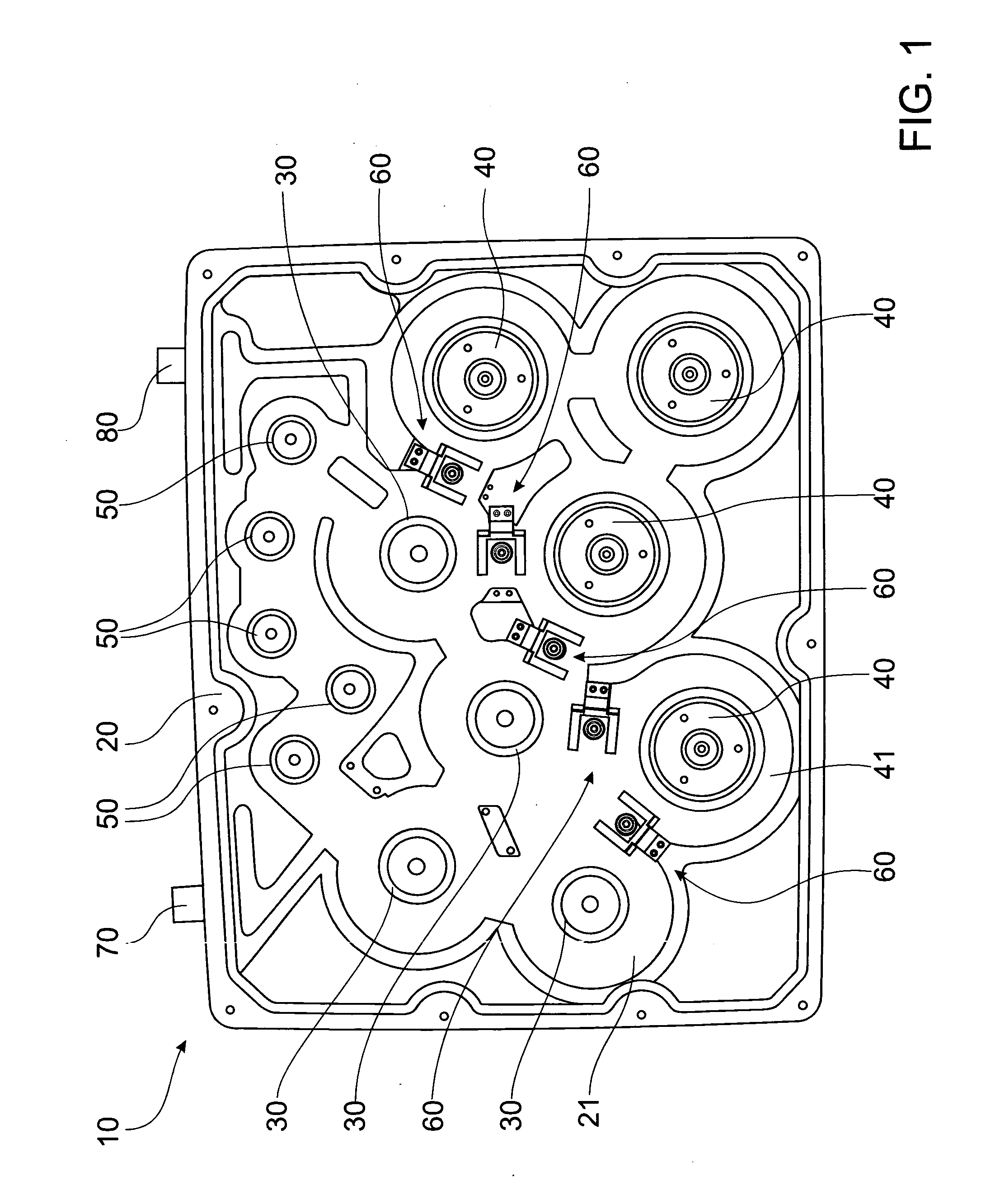
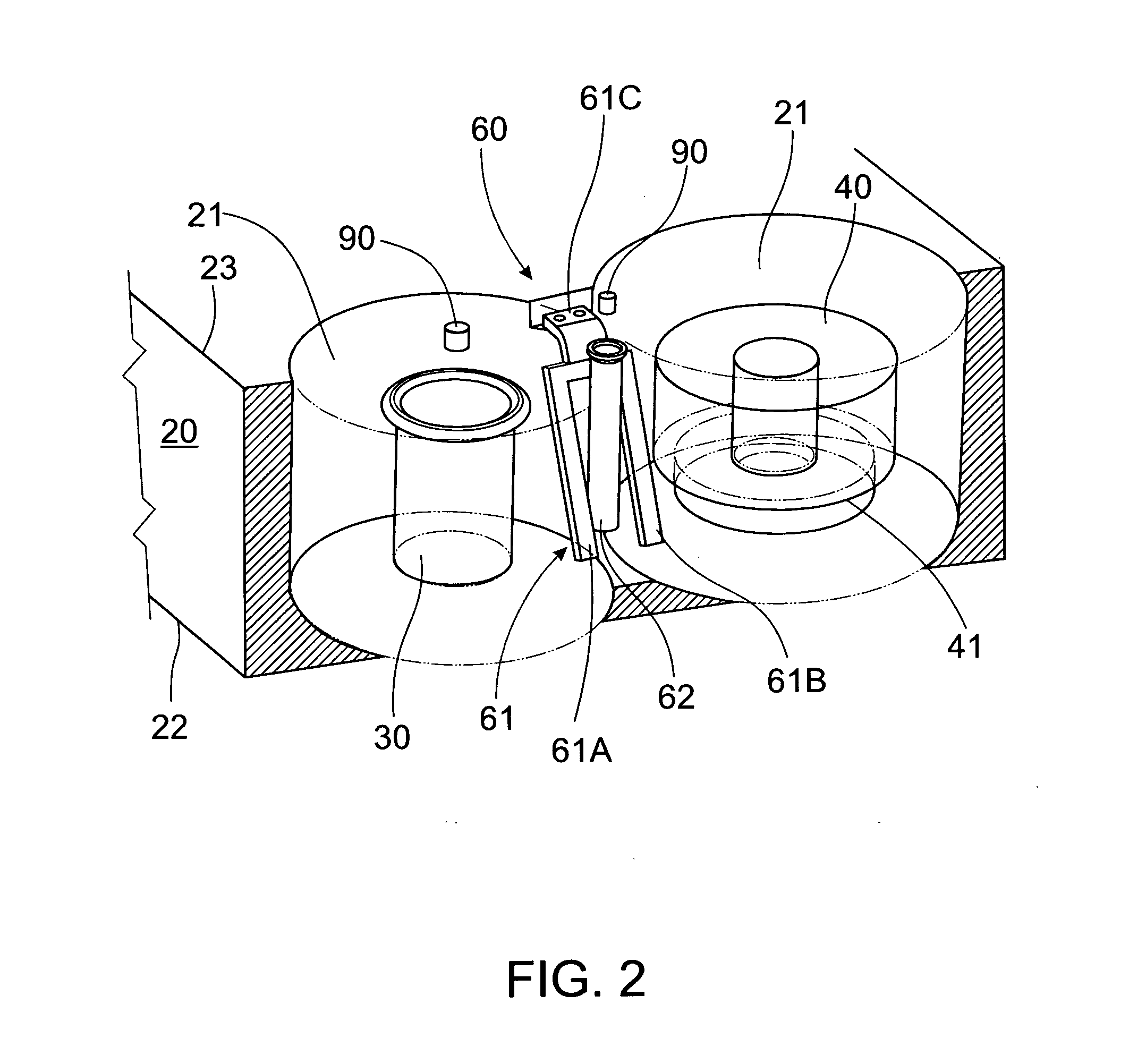
[0035]FIG. 1 shows a plan view of a filter 10 for filtering microwaves. The filter 10 includes a housing 20, a series of metallic resonators 30, a series of ceramic resonators 40, a series of receive resonators 50 a series of coupling structures 60 and a lid (not shown).

[0036]The housing 20 is made from aluminium or any suitable metal such as steel or metal coated plastic. A cavity 21 is formed in the housing 20 by machining or casting the housing 20. A first port 70 and a second port 80 are connected to the cavity 21.

[0037]The metallic resonators 30 and the receive resonators 50 are identical apart from their purpose and are made from aluminium. However any suitable metal such as steel or a metal coated plastic may be used. Resonators 30, 50 may be cast, drawn or machined or integrally moulded into the housing 20. Although the resonators 30, 50 are shown as being hollow it should be appreciated that they may also be solid or partially solid.

[0038]The ceramic resonators 40 are made ...


PUM

PropertyMeasurementUnit
Angleaaaaaaaaaa
Angleaaaaaaaaaa
Angleaaaaaaaaaa

Abstract

A coupling structure for a microwave filter including at least one coupling rod located adjacent a transformer.

Description

FIELD OF THE INVENTION[0001]This invention relates to microwave filters, in particular the invention relates to coupling structures used in microwave filters.BACKGROUND OF THE INVENTION[0002]Microwave filters are used extensively in radio communications, to ensure that signals from one band of the radio frequency (RF) spectrum do not encroach into another. This is particularly important when used in mobile phone base stations, where interference between bands may mean increased call drop out rates and a reduction in data transmission rates. This is especially the case between the WCDMA and GSM900 bands which are located adjacent each other and often causing substantial interference.[0003]Interference between the WCDMA and GSM900 bands may be reduced by increasing a guard band between the bands. One contributing factor to the size of guard band required is the band edge response of the filter. A sharper transition between the pass band and the reject band means that interference betw...

Claims


Application Information

Patent Timeline
IPC IPC(8): H01P1/20H01P11/00H01P5/00
CPCH01P1/2053Y10T29/49002H01P1/2084
Inventor BLAIR, CHRISTINE
Owner TRIASX PTY LTD
Why Eureka
Try Eureka