Light emitting device and bulb-type LED lamp

a technology of light emitting devices and led lamps, which is applied in the direction of coupling device connections, light source combinations, instruments, etc., can solve the problems of unfavorable possibility, additional work of placing diffusion sheets, and the efficiency of light radiation is deteriorated, so as to reduce the number of leds and reduce the light transmission rate

Inactive Publication Date: 2012-01-26
NITTO OPTICAL CO LTD +1
View PDF1 Cites 20 Cited by
  • Summary
  • Abstract
  • Description
  • Claims
  • Application Information

AI Technical Summary

Benefits of technology

[0018]According to the present invention, it becomes possible to diffuse and radiate light uniformly over an entire area

Problems solved by technology

Since the LED light bulb proposed in Patent Document 1 is equipped with a diffusion sheet placed on an external surface of a translucent globe, the diffusion sheet lowers a light transmission rate, and accordingly the LED light bulb has a disadvantage that an efficiency of light radiation becomes deteriorated

Method used


Image

  • Light emitting device and bulb-type LED lamp
  • Light emitting device and bulb-type LED lamp
  • Light emitting device and bulb-type LED lamp

Examples


first embodiment

[0042](Regarding a Bulb-Type LED Lamp 1 According to the Present Invention)

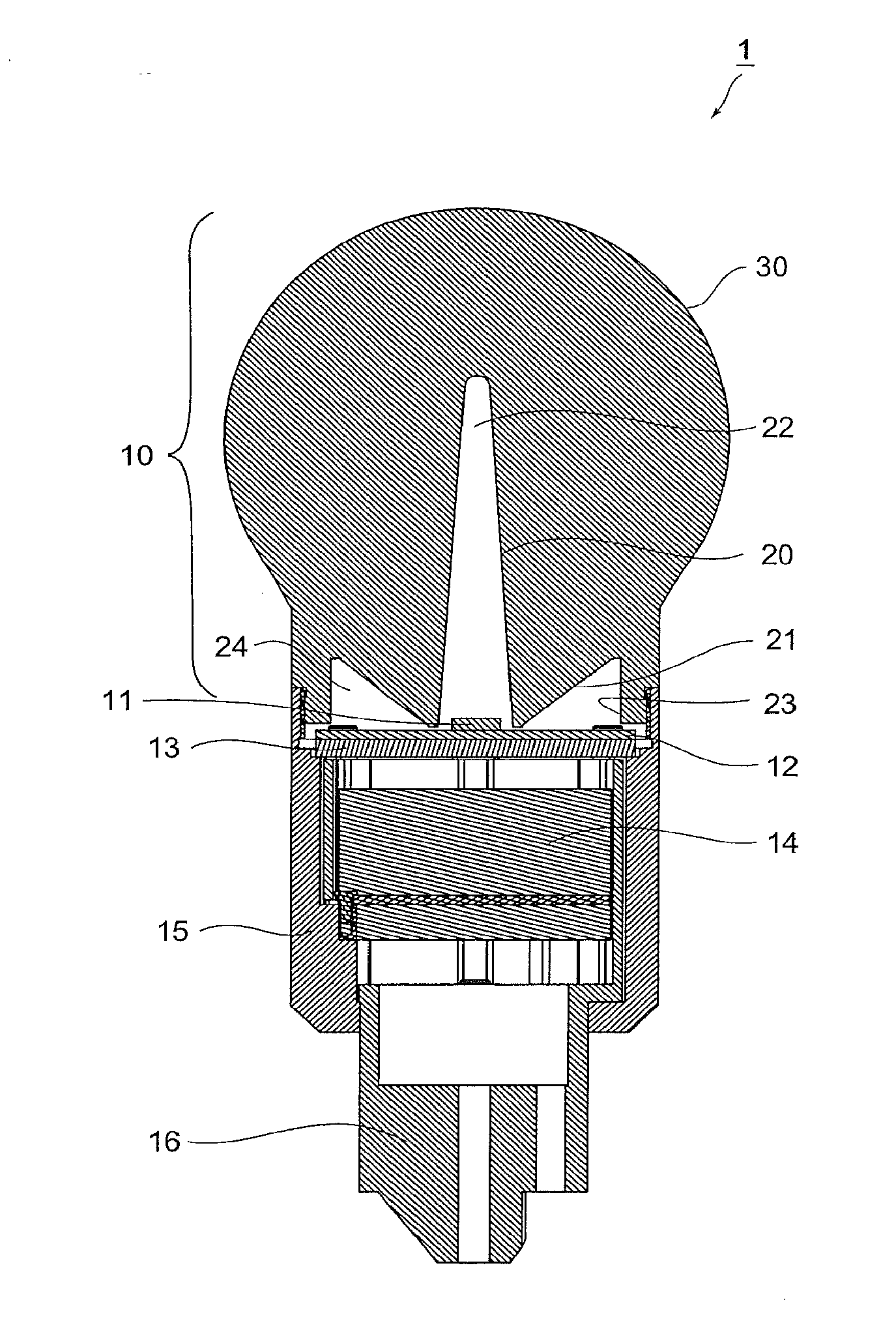
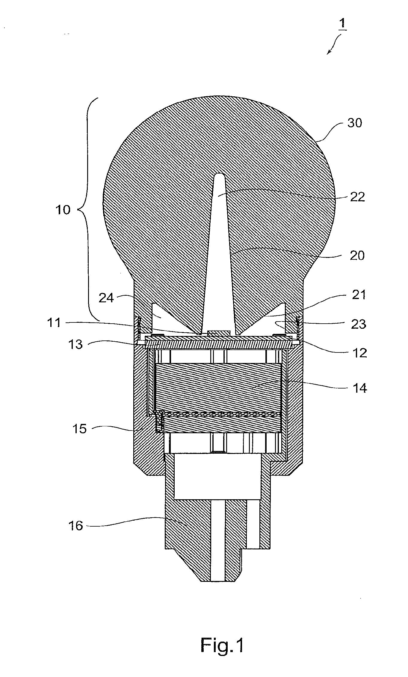
[0043]Explained below is a structure of a bulb-type LED lamp 1 according to a first embodiment of the present invention. A light emitting device is explained together with the explanation on the bulb-type LED lamp 1. The bulb-type LED lamp 1 principally comprises a light scattering / guiding globe 10 that contains light scattering particles, an LED 11, a circuit board 12, a heat dissipating plate 13, a power supply section 14, a heat dissipating cover 15, and a lamp base 16.

[0044]The light scattering / guiding globe 10 is shaped like a bulb globe with a light scattering / guiding material. Being different from a conventional bulb globe, the light scattering / guiding globe 10 is a solid component whose internal part is made solid. The light scattering / guiding globe 10 is a resin molded body, for example, made of transparent poly-methyl methacrylate (hereinafter abbreviated to “PMMA”). In the PMMA to be used for shapi...

second embodiment

[0076](Regarding a Bulb-Type LED Lamp 1A According to the Present Invention)

[0077]Explained below is a bulb-type LED lamp 1A according to a second embodiment of the present invention. FIG. 7 is a configuration drawing of the bulb-type LED lamp 1A. The bulb-type LED lamp 1A is partially different from the bulb-type LED lamp 1. In the following explanation; any member, which is identical or equivalent to that in the first embodiment, is explained by using the same or similar reference numeral, and then the explanation is omitted or simplified; and on the other hand any member, which is specific to the second embodiment, is mainly explained.

[0078]In the bulb-type LED lamp 1A, a light scattering / guiding globe 10A has a circular cylindrical shape. In other words, at least a part of the light scattering / guiding globe 10A is shaped like a circular cylinder; and an end of the circular cylinder, which is opposite to a side of the LED 11, is shaped like a convex lens.

[0079]Thus, an outer prof...

third embodiment

[0084](Regarding a Bulb-Type LED Lamp 1B According to the Present Invention)

[0085]Explained below is a bulb-type LED lamp 1B according to a third embodiment of the present invention. FIG. 12 is a configuration drawing of the bulb-type LED lamp 1B. The bulb-type LED lamp 1B is partially different from the bulb-type LED lamp 1. In the following explanation; any member, which is identical or equivalent to that in the first embodiment, is explained by using the same or similar reference numeral, and then the explanation is omitted or simplified; and on the other hand any member, which is specific to the third embodiment, is mainly explained.

[0086]In the bulb-type LED lamp 1B, a second light incoming surface 21B is different from the second light incoming surface 21 of the bulb-type LED lamp 1. Namely, between a bottom plane 22a of the first hollow section 22, being shaped conically, surrounded by the first light incoming surface 20B and the LED 11, the second light incoming surface 21B ...


PUM

PropertyMeasurementUnit
Coloraaaaaaaaaa
Depthaaaaaaaaaa
Efficiencyaaaaaaaaaa

Abstract

Provided is a light emitting device which can uniformly diffuse and radiate light from all the regions of the globe of an LED bulb without deteriorating light transmission efficiency. A light emitting device is provided with a light scattering/guiding globe and an LED which is disposed on one end of the light scattering/guiding globe. The light scattering/guiding globe is a body with no air released from the inside and is composed of a light scattering/guiding material having light scattering particles contained therein. The globe has the bottom surface on the side of the LED, and is provided with a first light incoming surface as a first hollow section, which is formed in a circular cone shape in the light outputting direction from the bottom surface.

Description

CROSS-REFERENCE TO RELATED APPLICATION[0001]The present application is a national phase of an International application No. PCT / JP2010 / 001918 filed on Mar. 17, 2010, which relates to and claims priority from Japanese patent application No. 2009-097103 filed on April 13. The contents of the International application and the Japanese application are incorporated herein by reference.BACKGROUND OF THE INVENTION[0002]1. Field of the Invention[0003]The present invention relates to a light emitting device and a bulb-type LED lamp.[0004]2. Description of Related Art[0005]A traditional filament bulb has a diffusion film formed on a glass bulb (a globe) for controlling the glare in order to prevent a high intensity of a point light source from causing a discomfort feeling on humans. In the meantime, a bulb-type fluorescent light has a light emitting property that an entire lamp emits fluorescent light, and therefore glaring can easily be controlled.[0006]On the other hand, taking advantage of...

Claims


Application Information

Patent Timeline
IPC IPC(8): F21V3/00
CPCF21K9/135F21V29/89F21V3/0436F21V5/041F21V23/023F21V23/04F21Y2101/02F21Y2103/022F21Y2113/005G02B5/0242G02B5/0278F21V29/20G02B19/0071G02B19/0028G02B19/0061F21V3/02F21K9/232F21Y2115/10F21Y2103/33F21Y2113/13F21V3/062F21V29/70
Inventor SHINOHARA, YOSHINORI
Owner NITTO OPTICAL CO LTD
Why Eureka
Try Eureka