
Radio Link Aggregation

a radio link and aggregation technology, applied in the field of communication, can solve the problems of not being able to transmit higher data rates over a single radio link, requiring a much higher sampling rate than the bandwidth of user data, and not being able to meet the requirements of high data ra

Active Publication Date: 2012-01-26
TELEFON AB LM ERICSSON (PUBL)
View PDF22 Cites 16 Cited by
  • Summary
  • Abstract
  • Description
  • Claims
  • Application Information

AI Technical Summary

Benefits of technology

The present invention provides improvements over prior art techniques of grouping or ungrouping traffic in communication networks. The network entity of the invention is a component of the network that handles traffic. It is responsible for organizing the traffic into groups and transmitting them over a defined connection. The network entity uses a scheduler to associate each symbol block of traffic with a corresponding output link in a one-to-one correspondence. This allows for efficient handling of traffic. The invention can be implemented in hardware, software or a combination of both. The technical effects of the invention include improved efficiency in managing network traffic and better utilization of network resources.

Problems solved by technology

Furthermore SONET / SDH radio systems typically install redundant links for radio protection switching.
However, traditional TDM radio links are not designed for such high bandwidth.
Technical reasons comprise limited resolution of available ADCs (analog-digital-converters) and / or DAC (digital-analog-converters), complex design of highly selective analog wideband filters, desired system modularity (i.e. possibility to extend the capacity later), trade-offs between modulation order and oscillator phase noise sensibility, new technologies as digital amplifier linearization which requires much higher sampling rate than the bandwidth of the user data, thermal problems, etc.
Under the circumstances described above it is clear that it is often not possible to transmit higher data rates over a single radio link.
However, the known techniques suffer from a limited bandwidth capacity limited to the capacity of the single therein described and suggested link.
However, the known mentioned implementation is not flexible and limited to very special cases, namely transmission of ST-4 over 2 or more radio links.
These systems are not very effective (e.g. SDH overhead, resource requirements for handling of many VCG's members).
Because of the SDH hierarchy these systems are designed for fixed link bandwidth which limits the use of adaptive modulation and coding.
With an asynchronous aggregation system it gets very complicated to handle adaptive modulation and coding.
Although we may foresee solving this problem by packet transmission with sequence numbers, still such a solution would result in causing more latency.
In particular the transmission of low rate TDM services in packets causes a high delay.
In summary, the prior art does not provide a resource efficient and flexible solution for aggregating data over a communication network.
With reference to radio links, furthermore, there is no radio system which makes an effective use of resources.

Method used


Image

  • Radio Link Aggregation
  • Radio Link Aggregation
  • Radio Link Aggregation

Examples


example a (

Low Rates Only for Explanation)

[0151]frame duration=1 ms

byte scheduling

3 Links:

[0152]Link payload rate A: 2 kbits / s

Link payload rate B: 5 kbits / s

Link payload rate C 1 kbits / s

Aggregation Payload rate: 8 kbits / s

2 Services:

[0153]Service rate A: 6 kbits / s

Service rate B: 2 kbits / s (e.g. Idle)

[0154]When applying the above example A to the algorithm of FIGS. 13A and 13B, the following results are produced as summarized in the below table.

Example A (Result): Service-Link-Mux TableIndexServiceIdLinkId112211312422512611712823

[0155]FIG. 14A shows the Service MUX table produced according to the algorithm of FIGS. 13A and 13B when applied to the example A illustrated above.

[0156]In particular, FIG. 14A illustrates steps for generating the Service-MUX table for Example A, with the following initialisation parameters.

Initialisation:

M:=2; LwSFP:=8;

LwCBR(1):=6; LwCBR(2):=2;

[0157]cbr(1):=6; cbr(2):=2;


PUM


Abstract

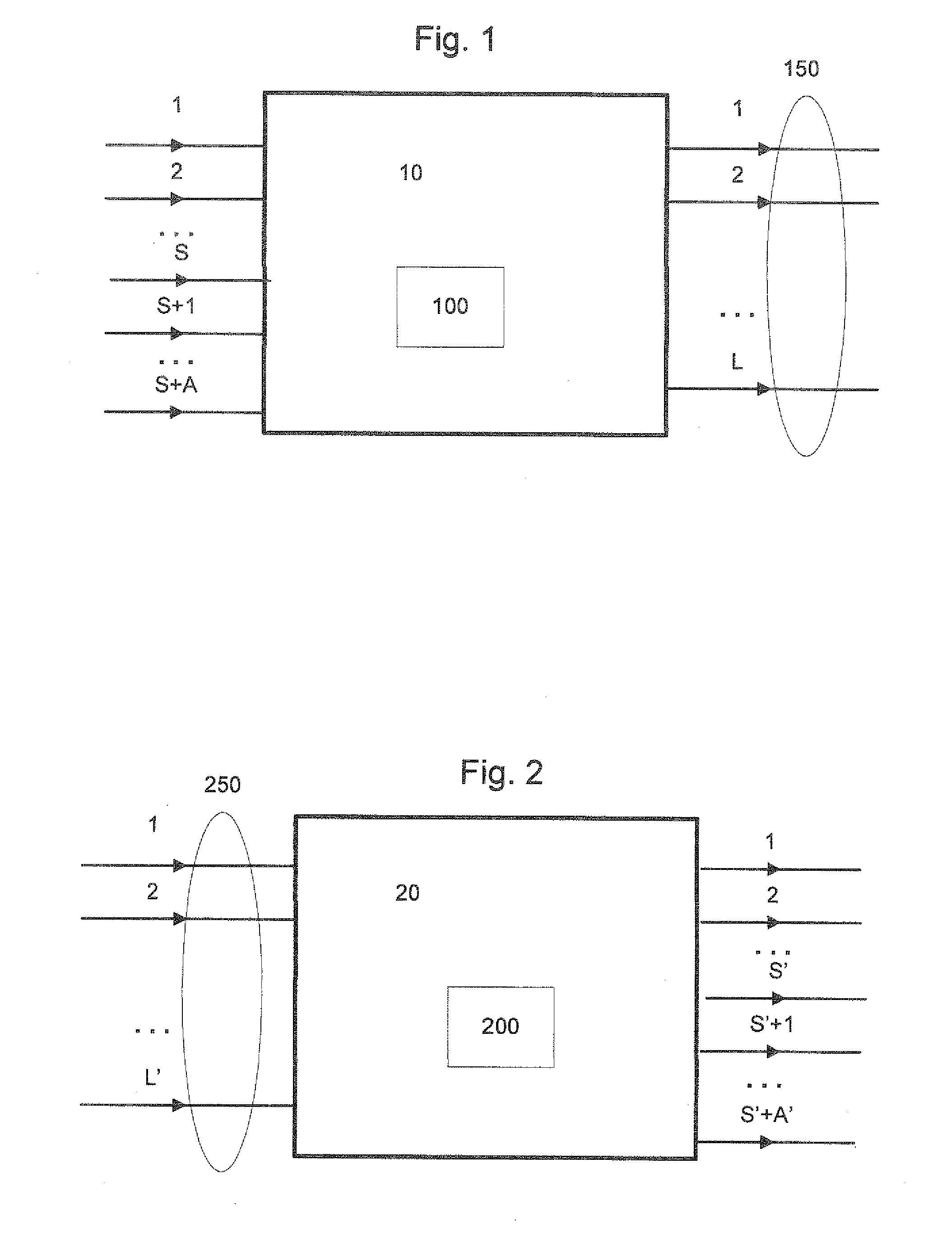
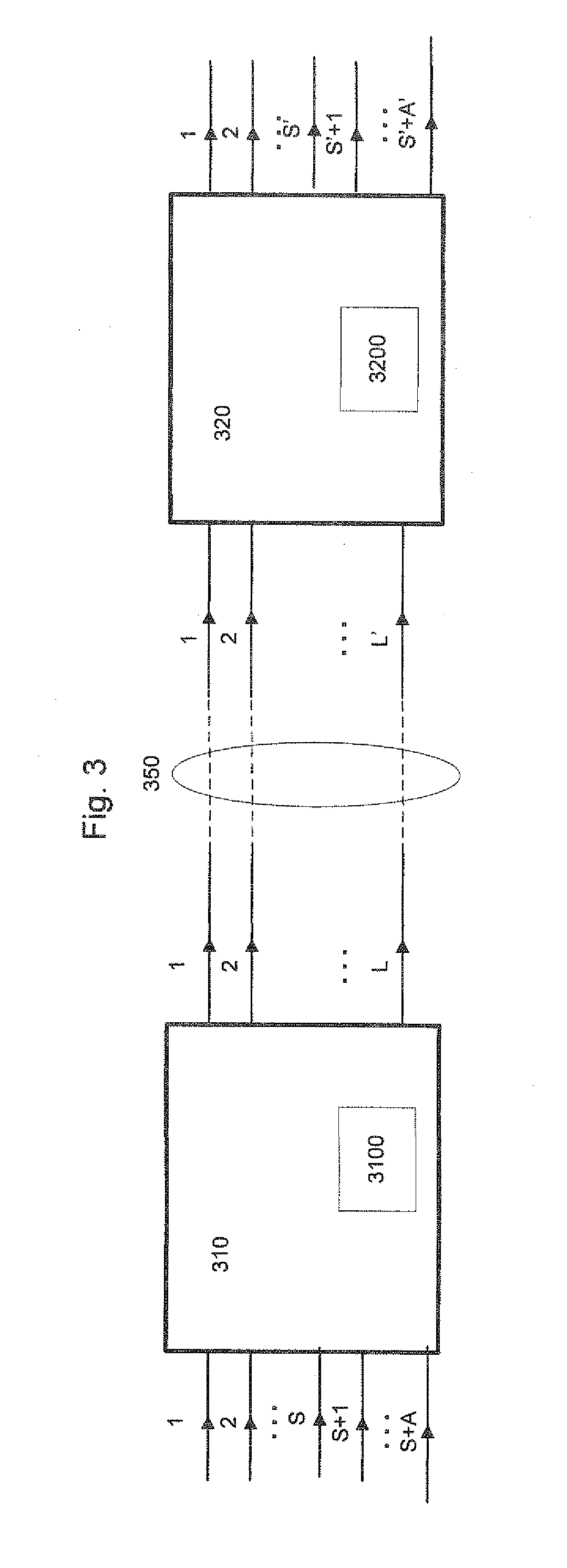
It is provided a network entity (10) for grouping traffic in a communication network onto a defined connection comprising a plurality of output links (1 . . . L), wherein the traffic comprises a plurality of input streams (1 . . . S+1 . . . S+A), each input stream carrying symbol blocks. The network entity further comprises a scheduler (100) for associating, for all symbol blocks that are to be transmitted during a predetermined time interval, each of the symbol blocks to be transmitted with a corresponding output link according to a one to one correspondence. It is also provided a corresponding network entity for ungrouping traffic, corresponding system and method.

Description

TECHNICAL FIELD[0001]The present invention relates to communication in a network and more particularly to a network entity for grouping traffic onto a defined connection, a network entity for ungrouping traffic in a communication network from a defined connection, a system for exchanging traffic in a communication network over a defined connection and corresponding methods.BACKGROUND[0002]The present invention relates to transmissions in a communication network and in particular it is concerned with multiplexing and bundling techniques for transmission in a communication network.[0003]Traditional networks are designed for TDM services (for instance SONET / SDH / PDH). These networks are typically designed for supporting peak usage of bandwidth requirements and require a high reliability. TDM systems must be designed with sufficient link margin to guarantee transmission even under worst case condition like rain and fading. Furthermore SONET / SDH radio systems typically install redundant l...

Claims


Application Information

Patent Timeline
Patent Type & Authority Applications(United States)
IPC IPC(8): G06F15/16H04L45/243H04W72/54
CPCH04L25/14H04L45/245H04W72/12H04W40/00H04W28/06
Inventor HELMKE, HOLGER
Owner TELEFON AB LM ERICSSON (PUBL)
Learn More