
Robotic mower housing

a robotic mower and housing technology, applied in the field of robotic mower housing, can solve the problems of components that may malfunction, exposed to harsh and adverse operating conditions,

Active Publication Date: 2012-02-02
DEERE & CO
View PDF6 Cites 49 Cited by
  • Summary
  • Abstract
  • Description
  • Claims
  • Application Information

AI Technical Summary

Benefits of technology

[0003]A robotic mower housing has a top cover and bottom chassis that includes a pair of walls, an outer wall and an inner wall, to protect electronics and / or other critical components that are housed inside the robotic mower. The double wall provides two barriers preventing moisture, dust, debris and other contaminants from reaching sensitive components including the vehicle control unit, boundary sensors and battery pack.

Problems solved by technology

As robotic mowers are increasingly used in different environments, they may be exposed to harsh and adverse operating conditions, including moisture from rain, sprinklers or ground water, and dirt, dust or other debris.
The components may malfunction if they are exposed to water, dirt, or dust.

Method used


Image

  • Robotic mower housing
  • Robotic mower housing
  • Robotic mower housing

Examples


Embodiment Construction

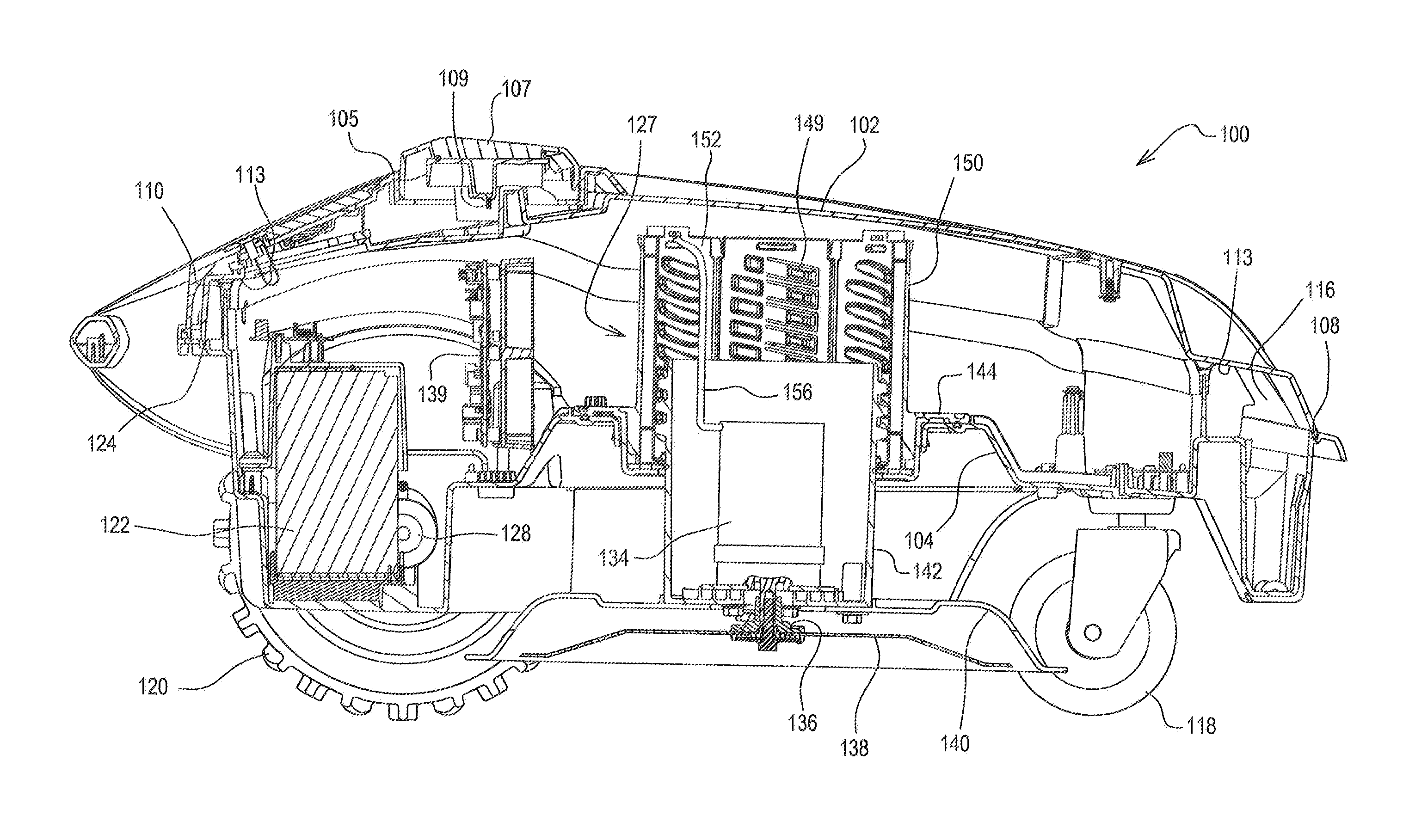
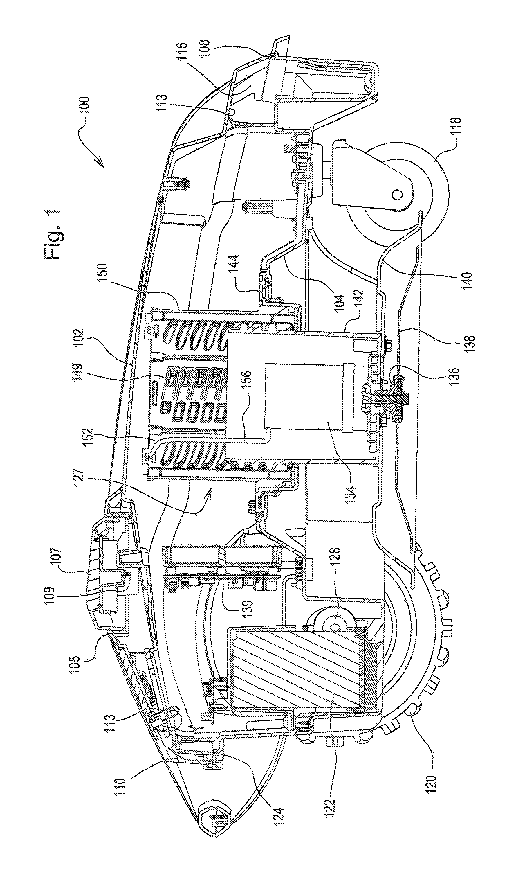
[0010]In one embodiment shown in FIG. 1, robotic mower 100 may be powered by battery pack 122 that may be charged periodically using a charging station. Battery pack 122 may store electrical energy used to operate a pair of variable speed electric motors 128 to turn a pair of traction drive wheels 120, rotate cutting blade 138, and power vehicle control unit 139 that may be programmed to command electric traction wheel motors 128 and operate functions of the robotic mower. Each traction wheel motor may be a DC brushed or DC brushless motor that controls one of the wheels.

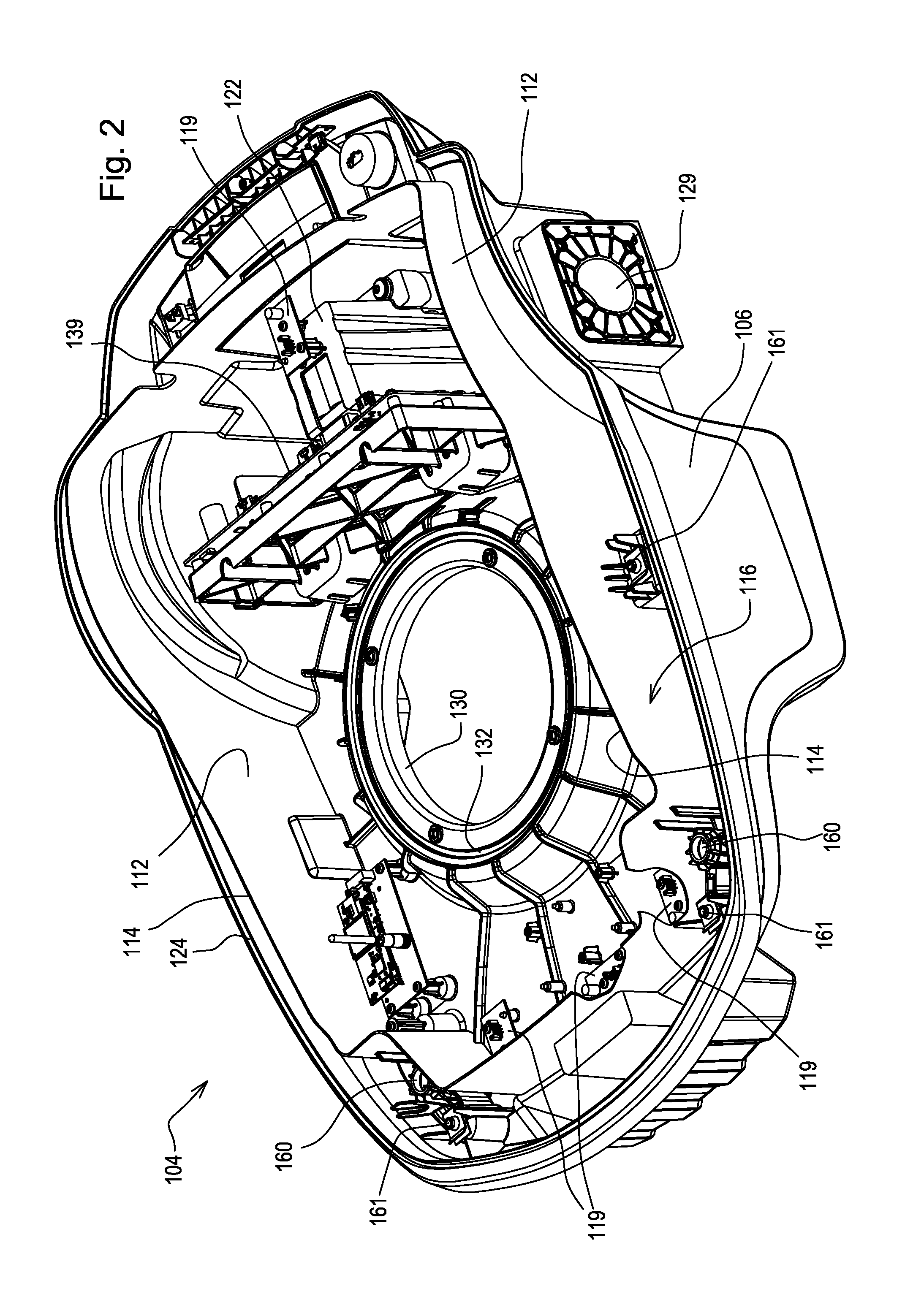
[0011]In one embodiment shown in FIGS. 1 and 3, top cover 102 may be removably attached and secured to bottom chassis 104. Control panel 105 may be removably attached to the top cover, and the control panel may be connected to the vehicle control unit for an operator to enter various commands using a keypad. A seal may be provided between the control panel and the top cover. Additionally, a stop button may be provid...


PUM


Abstract

A robotic mower housing includes a one piece molded bottom chassis having an inner wall and an outer wall. A top cover is removably attached to and covers the bottom chassis. An outer seal is provided between the outer wall of the bottom chassis and the top cover, and an inner seal between the inner wall of the bottom chassis and the top cover. The vehicle control unit and other electronic components may be located in the inner cavity inside the inner seal and an outer cavity between the outer seal and the inner seal.

Description

FIELD OF THE INVENTION[0001]This invention relates to robotic lawn mowers, and specifically to a housing for a robotic mower.BACKGROUND OF THE INVENTION[0002]As robotic mowers are increasingly used in different environments, they may be exposed to harsh and adverse operating conditions, including moisture from rain, sprinklers or ground water, and dirt, dust or other debris. Robotic mowers may include sensitive electronic components including microcontrollers for traction drive, cutting blade operation, and other critical functions. The components may malfunction if they are exposed to water, dirt, or dust. It also may be necessary to access these components periodically for service or replacement. A robotic mower housing is needed that protects critical electronic components from the conditions described without restricting access to them for service or replacement.SUMMARY OF THE INVENTION[0003]A robotic mower housing has a top cover and bottom chassis that includes a pair of walls...

Claims


Application Information

Patent Timeline
Patent Type & Authority Applications(United States)
IPC IPC(8): A01D34/81
CPCA01D34/008A01D34/81B60L1/003B60L3/0061B60L11/1803B60L11/1805B60L2260/28B60L15/20B60L2200/40B60L2220/16B60L2220/46B60L2240/36B60L2240/421B60L11/1877Y02T10/72B60L50/51B60L50/52B60L50/66Y02T10/64Y02T10/70
Inventor MESSINA, THOMAS M.ELHARDT, PAUL M.MOUSER, JOHN D.
Owner DEERE & CO
Learn More