Hydraulic tool that commands prime mover output

a technology of hydraulic pump and prime mover, which is applied in the direction of fluid couplings, servomotors, instruments, etc., can solve the problems of large engines that are noisy, fuel inefficient, and other smaller engines, such as the engine of a service pack, can be fuel inefficient at times

Active Publication Date: 2012-02-02
ILLINOIS TOOL WORKS INC
View PDF1 Cites 10 Cited by
  • Summary
  • Abstract
  • Description
  • Claims
  • Application Information

AI Technical Summary

Benefits of technology

[0013]In another embodiment, the present disclosure provides a system having a service pack unit. The service pack unit includes a drive, a hydraulic pump coupled to the drive, a first hydraulic output configured to supply a first flow of a hydraulic fluid from the hydraulic pump to a first hydraulic tool, a second hydraulic output configured to supply a second flow of the hydraulic fluid from the hydraulic pump to a second hydraulic tool, and a hydraulic tool control comprising a controller coupled to at least one electronically actuated valve, wherein the controller is configured to electronically adjust at least one electronically actuated valve to adjust a first flow rate of the first flow or a second flow rate of the second flow.
[0014]In another embodiment, the present disclosure provides a system having a hydraulic tool control including a hydraulic input configured to couple to a hydraulic pump, a first hydraulic output configured to supply a first flow of a hydraulic fluid from the hydraulic pump, through a first electronically actuated valve, and to a first hydraulic tool. The hydraulic tool control also includes a second hydraulic output configured to supply a second flow of the hydraulic fluid from the hydraulic pump, through a second electronically actuated valve, and to a second hydraulic tool. The hydraulic tool control is configured to electronically adjust the first and second electronically actuated valves to adjust a first flow rate of the first flow and a second flow rate of the second flow.
[0015]In another embodiment, the present disclosure provides a system having a service pack unit. The service pack unit includes a drive, a hydraulic pump coupled to the drive, a first hydraulic output configured to supply a first flow of a hydraulic fluid from the hydraulic pump to a first hydraulic tool, a second hydraulic output configured to supply a second flow of the hydraulic fluid from the hydraulic pump to a second hydraulic tool, and a hydraulic tool control having at least one electronically actuated valve. The hydraulic tool control is configured to electronically adjust at least one electronically actuated valve to adjust a first flow rate of the first flow or a second flow rate of the second flow.
[0016]In another embodiment, the present disclosure provides a system having a hydraulic supply system. The hydraulic supply system includes a drive, a hydraulic pump coupled to the drive, a first hydraulic output configured to supply a first flow of a hydraulic fluid from the hydraulic pump to a hydraulic lift, a second hydraulic output configured to supply a second flow of the hydraulic fluid from the hydraulic pump to a first hydraulic tool, and a hydraulic tool control having an electronic user interface, a controller coupled to the electronic user interface, and at least one electronically actuated valve coupled to the controller, wherein the electronic user interface has a display and an input device.

Problems solved by technology

Large engines are particularly noisy, and can be significantly over powered for certain uses, causing them to be fuel inefficient in some instances.
Further, other smaller engines, such as the engine of a service pack, can be fuel inefficient at times. For example, a typical hydraulic system used to power a crane and other hydraulic tools may be powered by an engine.
In such arrangements, there may either be too much power or too little power for the hydraulic tools.
Additionally, the use of full engine and hydraulic output is often power-inefficient, which can reduce the life of the engine and hydraulic parts.
When there is too little power, the user may not be able to utilize the full output of the hydraulic tools, and is only able to use one tool at a time.
The careful manual adjustments may be difficult for the user, and can be inaccurate.
Because some hydraulic tools may be connected to the hydraulic system by long hydraulic lines, this may result in inefficiencies as the user walks back and forth from the work area to the system.

Method used


Image

  • Hydraulic tool that commands prime mover output
  • Hydraulic tool that commands prime mover output
  • Hydraulic tool that commands prime mover output

Examples


Embodiment Construction

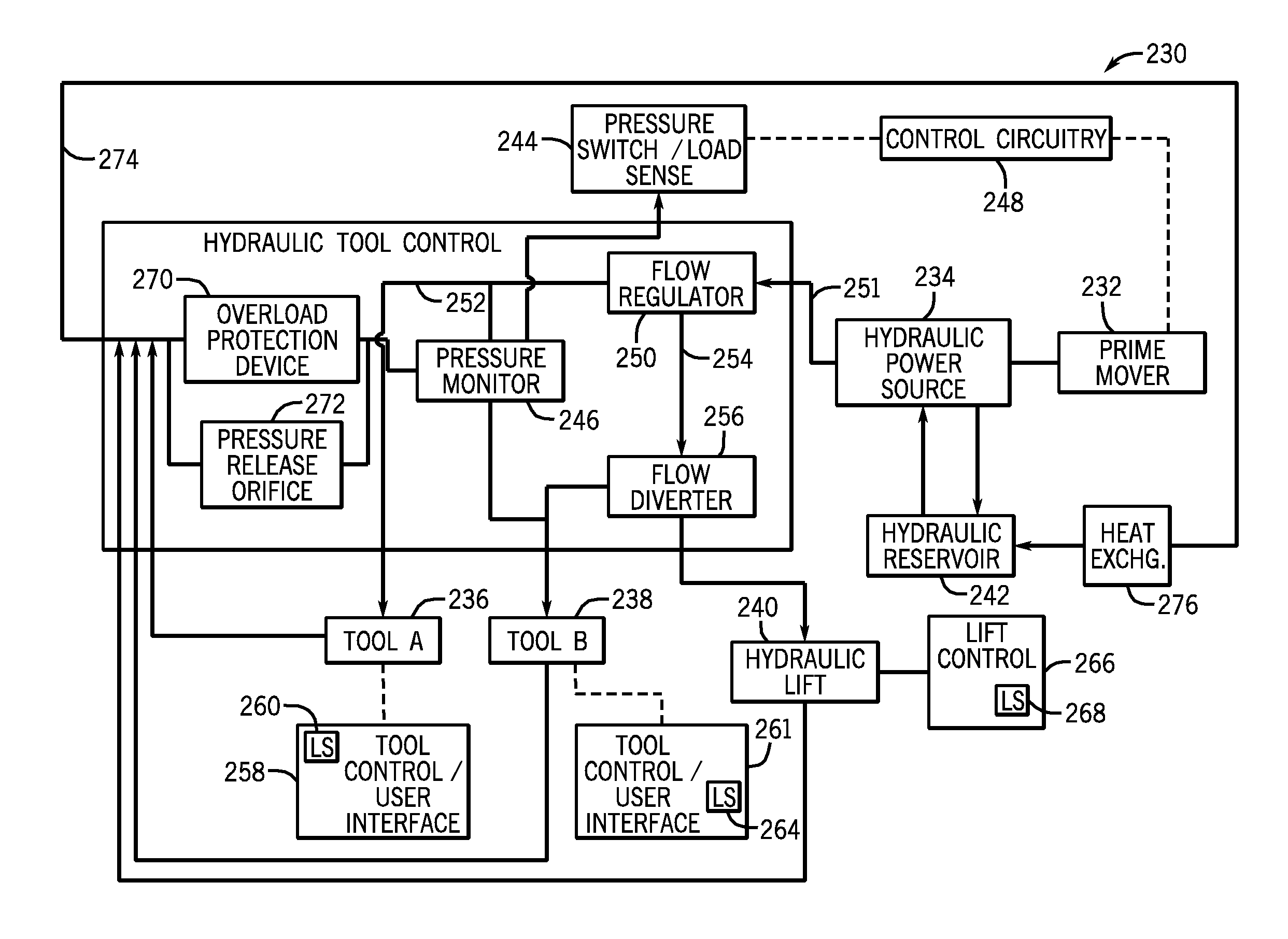
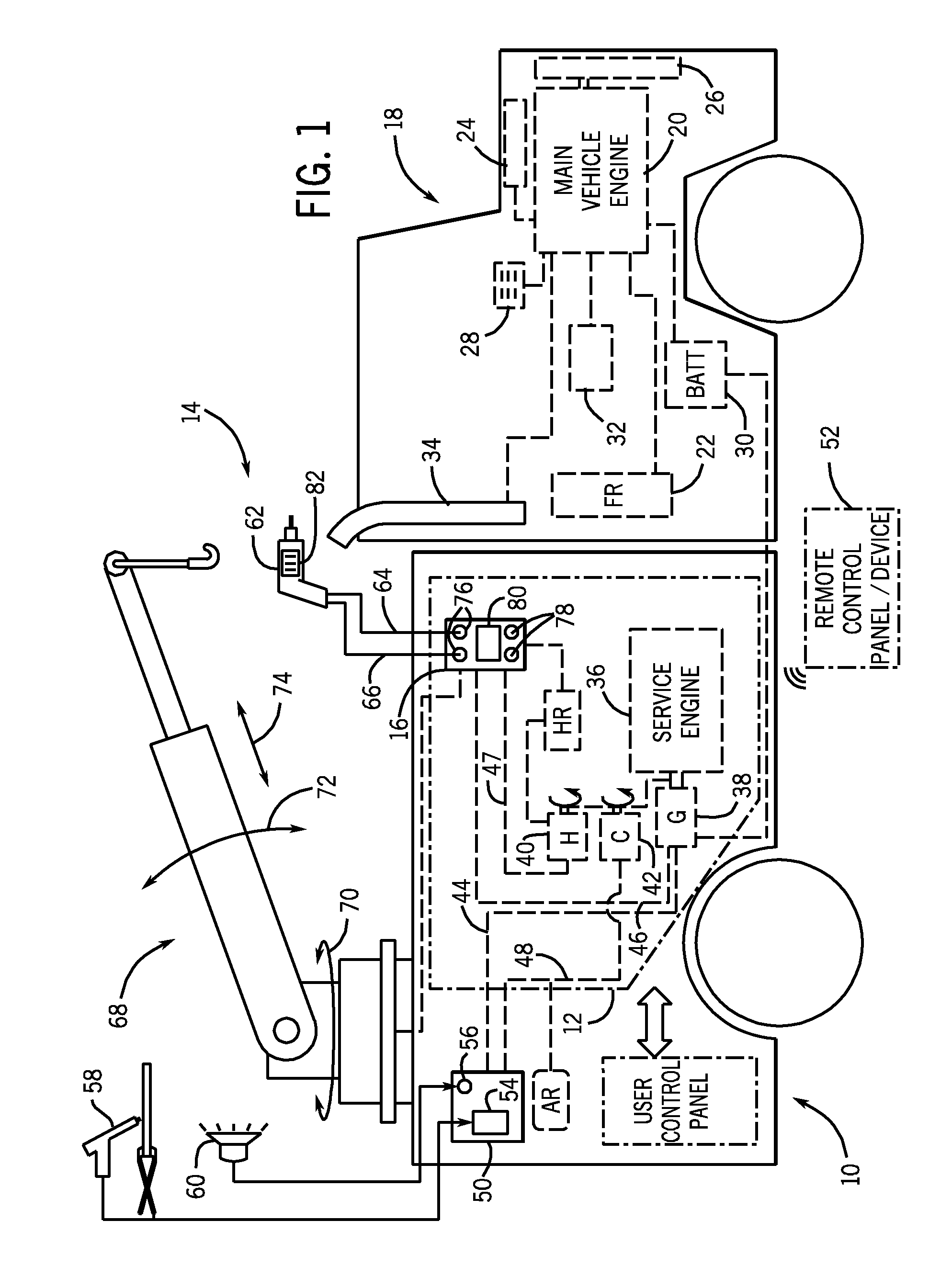
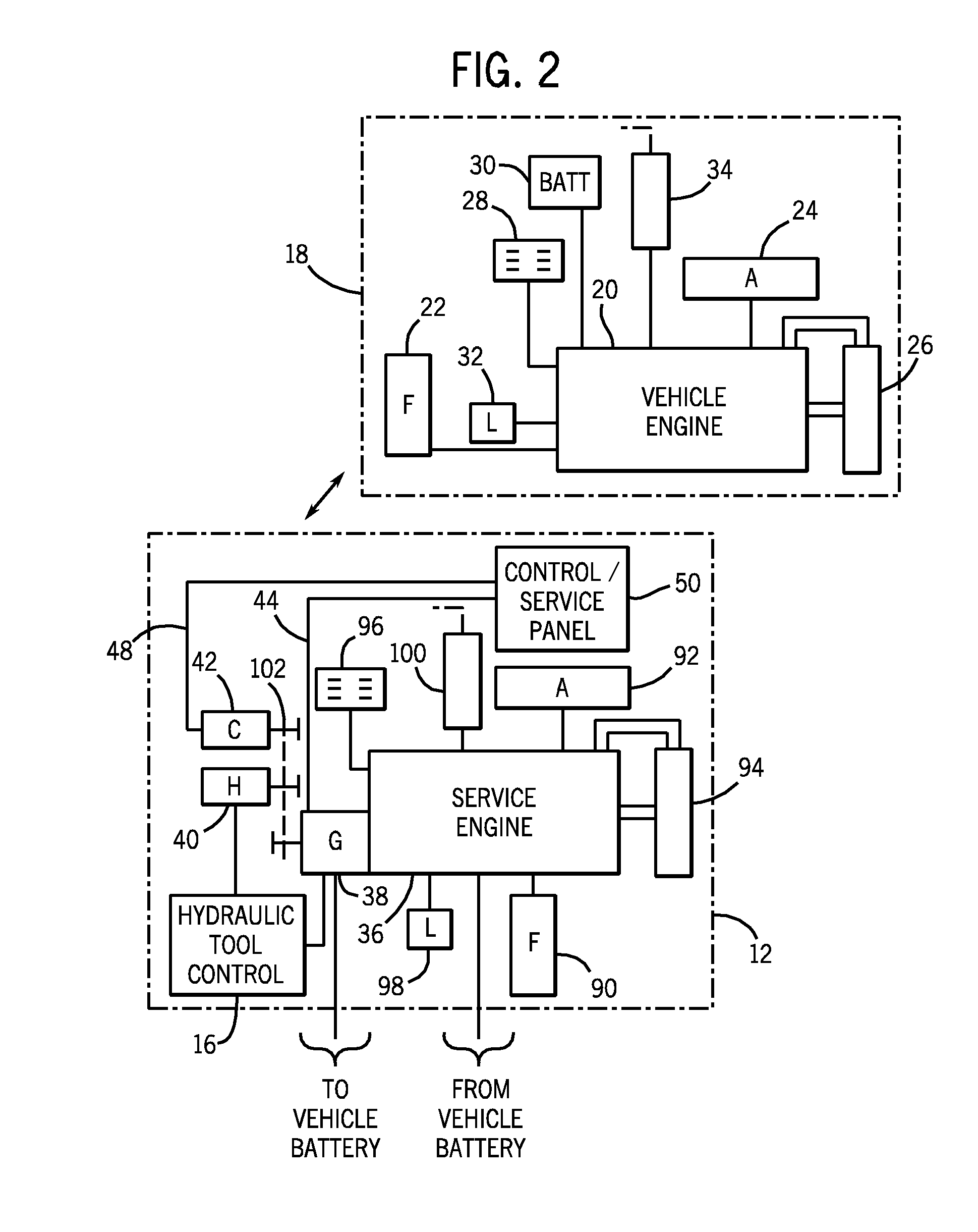
[0039]As discussed below, the present disclosure provides a uniquely effective solution to the control of hydraulic output in various applications. Thus, the disclosed embodiments relate or deal with any application where a prime mover or power source that is engine driven intermittently powers a hydraulic load or a combination of hydraulic loads. In certain embodiments, the disclosed hydraulic output control techniques may be used with various service packs and / or hydraulic pumps to prevent unnecessary or wasteful use of (and exhaust emissions by) a power source that is coupled to multiple loads, specifically one or more hydraulic loads. The present disclosure also provides embodiments that allow the use of multiple hydraulic tools simultaneously. For example, the disclosed embodiments may be used in combination with any and all of the embodiments set forth in U.S. application Ser. No. 11 / 742,399, filed on Apr. 30, 2007, and entitled “ENGINE-DRIVEN AIR COMPRESSOR / GENERATOR LOAD PRI...


PUM

PropertyMeasurementUnit
pressureaaaaaaaaaa
speedaaaaaaaaaa
pressureaaaaaaaaaa

Abstract

The present disclosure provides embodiments directed towards a system for the control of hydraulic output by a hydraulic power source. In one embodiment, a system is provided. The system includes a hydraulic supply system having a drive, a hydraulic pump coupled to the drive, a first hydraulic output configured to supply a first flow of a hydraulic fluid from the hydraulic pump to a hydraulic lift, a second hydraulic output configured to supply a second flow of the hydraulic fluid from the hydraulic pump to a first hydraulic tool, and a controller configured to adjust a speed of the drive in response to a feedback indicative of a first load by the hydraulic lift, a second load by the first hydraulic tool, or a combination thereof.

Description

CROSS REFERENCE TO RELATED APPLICATIONS[0001]This application claims the benefit of U.S. Provisional Patent Application Ser. No. 61 / 368,362, entitled “HYDRAULIC TOOL THAT COMMANDS PRIME MOVER OUTPUT,” filed on Jul. 28, 2010, U.S. Provisional Patent Application Ser. No. 61 / 368,369, entitled “HYDRAULIC TOOL THAT SWITCHES OUTPUT,” filed on Jul. 28, 2010, U.S. Provisional Patent Application Ser. No. 61 / 368,375, entitled “HYDRAULIC TOOL CONTROL WITH ELECTRONICALLY ADJUSTABLE FLOW,” filed on Jul. 28, 2010, U.S. Provisional Patent Application Ser. No. 61 / 368,383, entitled “OPERATOR INTERFACE FOR HYDRAULIC TOOL CONTROL,” filed on Jul. 28, 2010, all of which are herein incorporated by reference in their entirety.BACKGROUND[0002]The present embodiments relate generally to power and flow management for an engine and a hydraulic pump used for powering hydraulic loads, such as hydraulic tools and / or cranes. More specifically, the present disclosure relates to the electronic control of engine spe...

Claims


Application Information

Patent Timeline
Patent Type & Authority Applications(United States)
IPC IPC(8): F15B21/00
CPCB23K9/1006B23K9/164F15B11/162F15B2211/4053F15B2211/426G01M3/2815F15B2211/665F15B2211/6654F15B2211/6658F15B2211/7135F15B2211/781F15B2211/6346B60W30/1888B60W2300/16F15B2211/6326F15B2211/6651
Inventor PETERS, MARK EDWINRENNER, ROSS
Owner ILLINOIS TOOL WORKS INC
Why Eureka
Try Eureka