Direct-current motor and hub unit

a technology of direct-current motors and hub units, which is applied in the direction of electric devices, propulsion by batteries/cells, cycles, etc., can solve the problems of motors that are liable to suffer from dimensional variations occurring in opposing directions, bearings are liable to be strained, and impair the parallelism between

Active Publication Date: 2012-02-02
SANYO ELECTRIC CO LTD +1
View PDF10 Cites 8 Cited by
  • Summary
  • Abstract
  • Description
  • Claims
  • Application Information

AI Technical Summary

Benefits of technology

[0007]In view of the foregoing, it is an object of the present invention to provide a direct-current motor which includes a stator retained in a motor case and is free from the overheat of the stator and the dimensional variations, and to provide a hub unit.
[0018]This prevents the overheat of the stator, and suppresses the dimensional variations.
[0019]With the provision of the bulges on the stator, the stator has a greater diameter at the bulges. Therefore, the size of the rotor can be correspondingly increased, permitting the motor to have a higher output and a higher efficiency. Particularly, where the stator has a greater size, the slot length of the stator can be increased. Correspondingly, wires each having a greater diameter can be wound a greater number of turns to form coils in the stator, thereby further increasing the output and the efficiency of the motor.
[0020]The bulges project outward of the inner peripheral surface of the motor case through the windows and, therefore, are easily exposed to air outside the motor case. This makes it possible to effectively cool the stator at the bulges.
[0021]The stator fixing screw holes are respectively provided in outer portions of the bulges projecting outward of the inner peripheral surface of the motor case. Therefore, the fixing screws are disposed apart from a magnetic path generated by the stator. This prevents the fixing screw holes from interfering with the magnetic path.
[0022]Further, protuberances provided around the windows of the motor case and raised inward from the motor case abut against the stator accommodated in the motor case to radially position the stator. Portions of the motor case formed with the protuberances each have a correspondingly greater wall thickness, so that portions of the motor case in abutment against the stator are reinforced.

Problems solved by technology

Therefore, the motor is liable to suffer from dimensional variations occurring in an opposing direction of the pair of end plates depending on the state of the clad metal plate clamped between the pair of end plates and an error in the thickness of the clad metal plate.
The variations result in positional offset of the bearings of the respective end plates (in other words, the variations impair the parallelism between the bearings).
If the bearings rotatably support the rotation shaft of the rotor with the positional offset, the bearings are liable to be strained.

Method used


Image

  • Direct-current motor and hub unit
  • Direct-current motor and hub unit
  • Direct-current motor and hub unit

Examples


Embodiment Construction

[0033]A specific embodiment of the present invention will hereinafter be described with reference to the attached drawings.

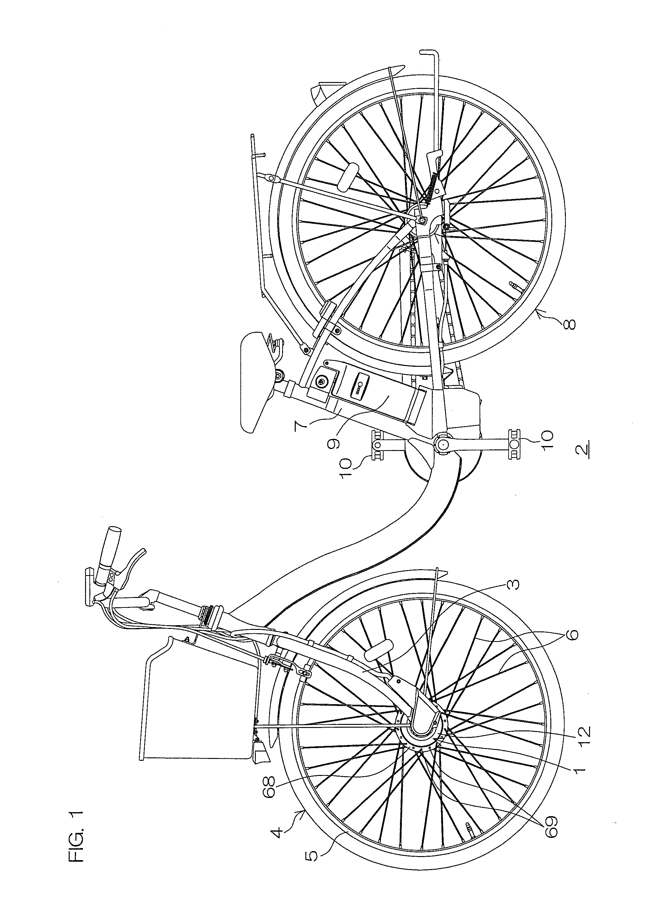
[0034]FIG. 1 is a left side view of an electrically assisted bicycle 2 including a hub unit 1 according to the embodiment of the present invention.

[0035]Referring to FIG. 1, the hub unit 1 is attached to distal ends of a front fork 3 of the electrically assisted bicycle 2, and connected to a rim 5 of a front wheel 4 by spokes 6. In the electrically assisted bicycle 2, a battery 9 is mounted between a seat post 7 and a rear wheel 8. In the electrically assisted bicycle 2, a sensor (not shown) is provided in portion on which a pedaling force of pedals 10 is applied. When the sensor senses, that a load acting on the pedals 10 reaches a predetermined level, power supply to a motor 11 (see FIG. 2 to be described later) of the hub unit 1 from the battery 9 is turned on.

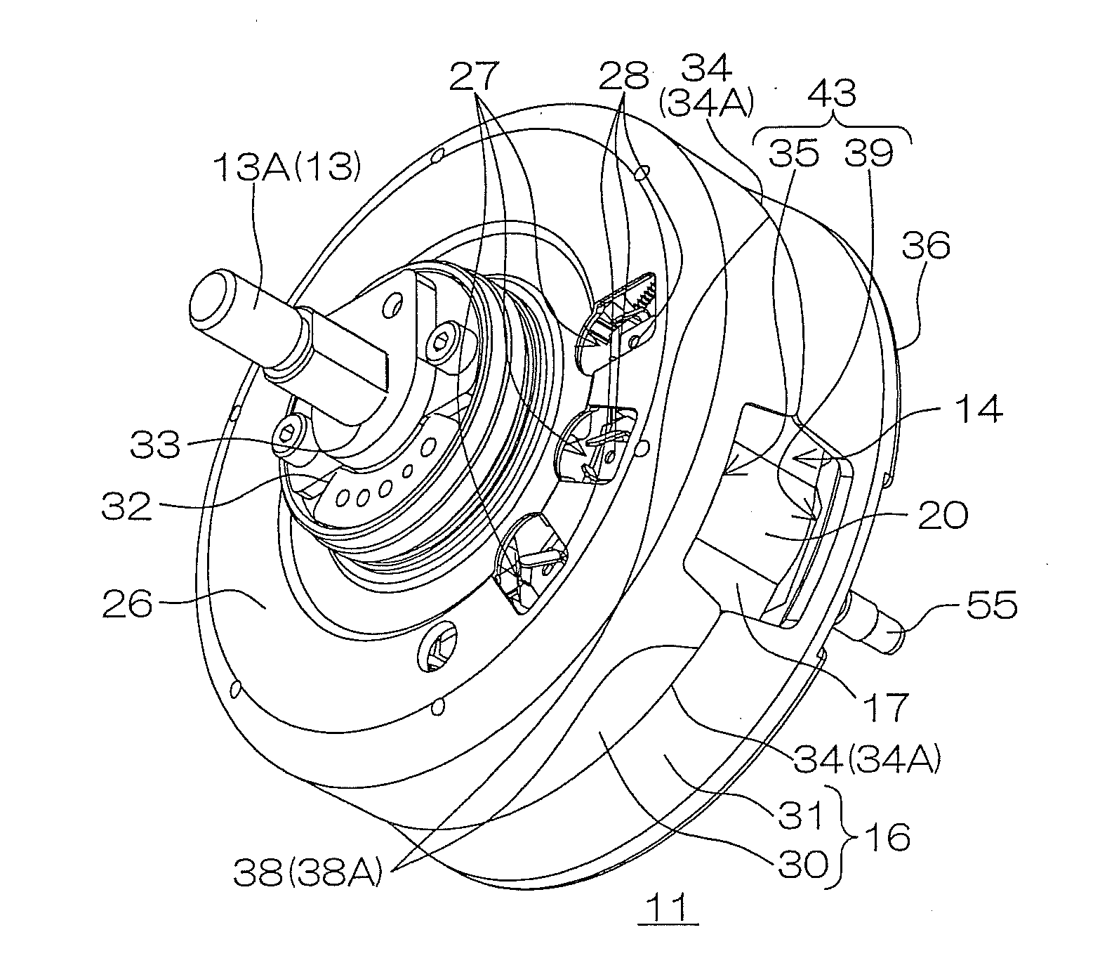
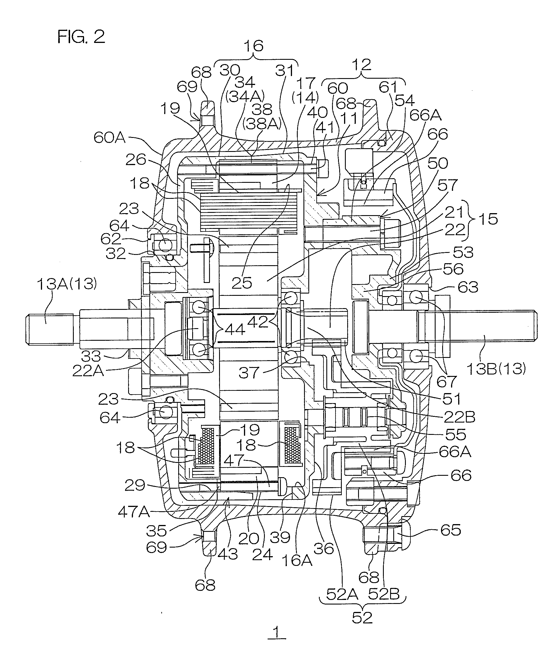
[0036]FIG. 2 is a sectional view of the hub unit 1. FIG. 3(a) is a right side view of the motor 11, ...


PUM


Abstract

In a motor, a motor case includes a first case and a second case separable from each other in a direction of an axis of a rotation shaft of a rotor. The first case and the second case each have cut-away portions extending parallel to the axis from a separation edge (open side edge) thereof. The separation edges of the first and second cases each have abutment portions not formed with the cut-away portions, and the abutment portions of the first case respectively abut against the abutment portions of the second case. The cut-away portions cooperatively define a plurality of windows disposed in a periphery of the motor case. The stator has a plurality of bulges projecting radially outward from a peripheral surface thereof in association with the windows.

Description

TECHNICAL FIELD[0001]The present invention relates to a direct-current motor and a hub unit.BACKGROUND ART[0002]A hub unit is known, which includes a direct-current motor and is mounted on a wheel of an electrically assisted bicycle (see, for example, JP-A-2005-335535).[0003]A hub unit disclosed in JP-A-2005-335535 essentially includes a motor including a stator and a rotor, and a hub accommodating the motor therein and rotatively driven by rotation of the rotor. A wheel on which the hub unit is mounted is rotated by the rotative driving of the hub.[0004]The motor includes a motor housing (motor case) which retains the stator. The motor housing includes a pair of end plates disposed in opposed relation on opposite sides of a clad metal plate of the stator. The end plates are clamped against each other by bolts with the clad metal plate being held therebetween, whereby the stator is retained in the motor housing with its outer peripheral surface being open to an interior of the hub b...

Claims


Application Information

Patent Timeline
Patent Type & Authority Applications(United States)
IPC IPC(8): H02K7/14H02K7/116H02K5/04
CPCB62M6/65Y02T10/705H02K5/04H02K5/1732H02K7/116H02K15/16Y02T10/86Y02T10/641B60L11/1877B60L2220/44B60L2260/28B60L11/007B60L2200/12H02K7/14Y02T10/7005H02K1/185B60L50/20B60L50/66Y02T10/64Y02T10/70
Inventor ADACHI, RYOHEI
Owner SANYO ELECTRIC CO LTD
Why Eureka
Try Eureka