
Surveillance camera system having camera malfunction detection function

a surveillance camera and malfunction detection technology, applied in the field of video surveillance systems with malfunction detection functions, can solve the problems of easy misreporting of normal video such as movement of a person, mainly detection of occlusion of the lens,

Inactive Publication Date: 2012-02-02
HITACHI INFORMATION & CONTROL SOLUTIONS LTD
View PDF2 Cites 45 Cited by
  • Summary
  • Abstract
  • Description
  • Claims
  • Application Information

AI Technical Summary

Benefits of technology

[0010]It is an object of the present invention to improve the above-described problems, and by reporting a malfunction detection of the surveillance camera and its type to provide a surveillance camera system which realizes a malfunction return or improving the efficiency of services such as maintenance and check.
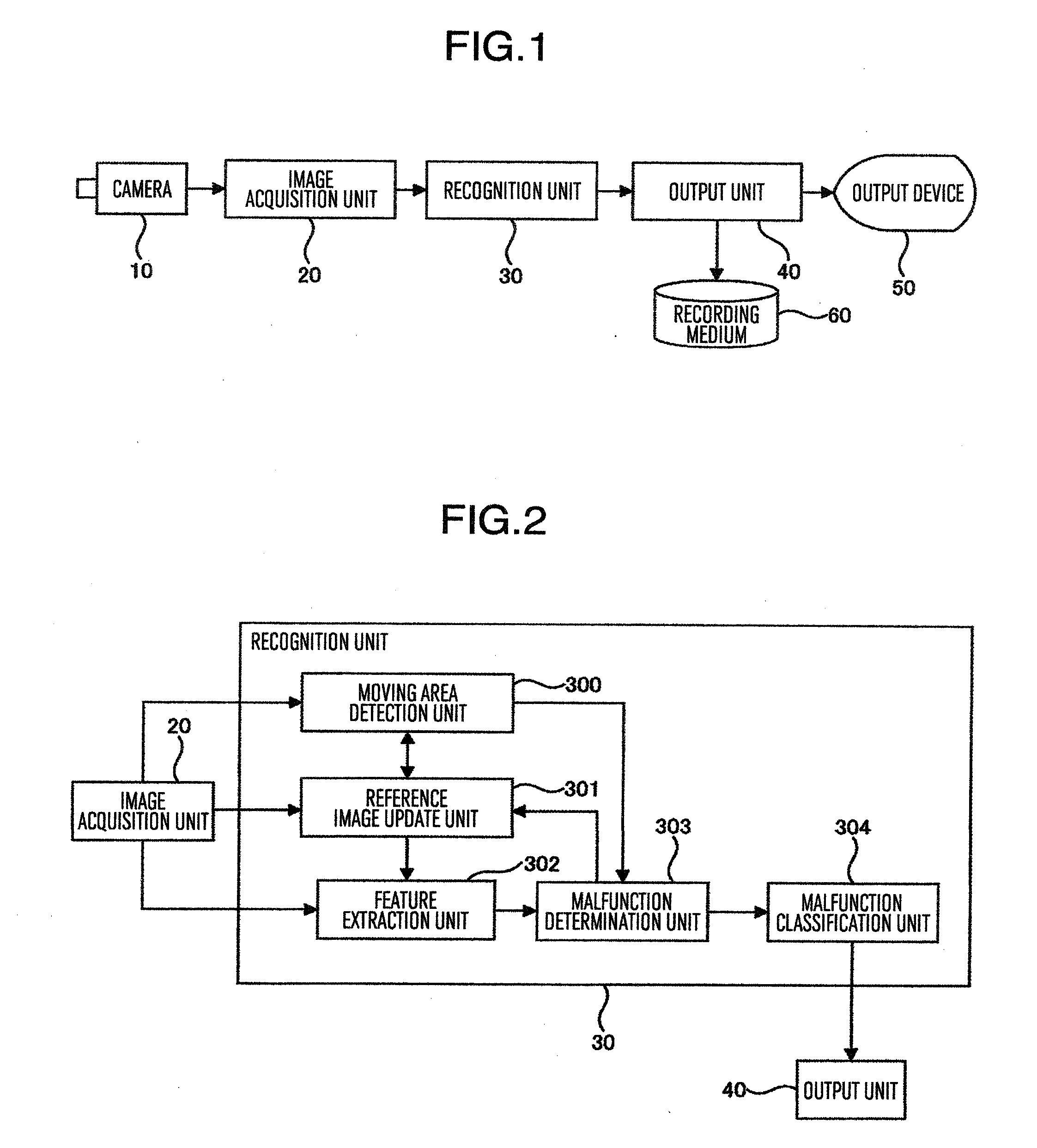
[0022]According to the present invention, when using the features and moving area of the entire input image and reference image and those of blocks divided into multiple pieces, the camera surveillance system can detect and classify various camera malfunctions such as partial occlusion, entire occlusion, camera angle shift (deviation in the camera direction), defocus, noise, and halation. Further, the efficient camera surveillance system which supports job efficiency of return from a malfunction, maintenance, and check can be provided.

Problems solved by technology

Therefore, in the conventional methods, only the occlusion of the lens can be mainly detected among the camera malfunctions.
However, as the type of the camera malfunction, the surveillance camera system having the camera malfunction detection function has to cope with various types of camera malfunction such as partial occlusion, entire occlusion, camera angle shift (deviation in the camera direction), defocus, noise, and halation (overexposure).
Further, there arises a problem that in the above-described conventional method, a normal video such as movement of a person is easy to be misreported.
Since a change in the luminance can be caused also by the movement of the person, there is a high possibility that the above is detected as the camera malfunction in a place where a lot of people frequently go in and out.

Method used


Image

  • Surveillance camera system having camera malfunction detection function
  • Surveillance camera system having camera malfunction detection function
  • Surveillance camera system having camera malfunction detection function

Examples


Embodiment Construction

[0040]Hereinafter, preferred embodiments of the present invention will be described with reference to the accompanying drawings of the embodiments. In each drawing, the same reference numerals as those of the first embodiment are given to the same or similar components as in the first embodiment, and the description will be omitted.

[0041]FIG. 1 illustrates the entire configuration of one embodiment of the present invention. FIG. 1 illustrates a configuration in the case where the present invention is applied to a surveillance camera system (video surveillance system) configured by a camera, a recording medium, and an output device. The surveillance camera system has an electric computer system including a CPU, memories, and LSIs as hardware, and is designed so as to perform each function. Here, the surveillance camera system is not expressed in constitutional unit of hardware, and each function configured by the hardware and software is expressed by blocks.

[0042]The surveillance cam...


PUM


Abstract

A camera surveillance system having a camera malfunction function includes an entire feature extraction unit to extract each entire feature from an input image and a reference image; a block feature extraction unit to extract block features being features of each block from images after the block division of the input image and the reference image divided into blocks by a block division unit; and a malfunction determination unit to calculate a first variation between the entire features of the reference image and the entire features of the input image, and a second variation between the block features of the reference image and the block features of the input image, to determine a camera malfunction by using a threshold, and output information indicating a type of the camera malfunction for each block.

Description

BACKGROUND OF THE INVENTION[0001]The present invention relates to a video surveillance system having a camera malfunction detection function of detecting a video acquisition failure due to an obstruction to a camera or equipment fault in a video surveillance system (surveillance camera system) which acquires videos from an imaging device such as a camera and has a function of intruder detection by image recognition.[0002]The video surveillance system has a function of detecting a moving object such as a person and vehicle which appear in a surveillance area based on image recognition from a video acquired from a camera. By using detection results, the video surveillance system draw a warder to attention by using a function of storing only videos in which moving objects appear, a display of a warning icon on a display device, or ringing of a buzzer. Therefore, the video surveillance system serves to reduce a load of a watching service in which a continuous confirmation work is necess...

Claims


Application Information

Patent Timeline
IPC IPC(8): H04N7/18G06V10/30
CPCG06K9/00771H04N7/181G06K9/40G06V20/52G06V10/30
Inventor ITOH, MASAYALI, YUANSAEKI, TAKASHISUDA, YASUHIRO
Owner HITACHI INFORMATION & CONTROL SOLUTIONS LTD
Learn More