Omni-directional channeling of liquids for passive convection in LED bulbs

a technology of led bulbs and liquids, applied in the direction of lighting elements, semiconductor devices of light sources, lighting and heating apparatus, etc., can solve the problems of % of power loss, inefficiency of incandescent bulbs, etc., and achieve the effect of facilitating a passive convective flow

Inactive Publication Date: 2012-02-02
SWITCH BULB CO INC
View PDF13 Cites 21 Cited by
  • Summary
  • Abstract
  • Description
  • Claims
  • Application Information

AI Technical Summary

Benefits of technology

[0010]In one exemplary embodiment, an LED bulb has a base, a shell connected to the base, and a thermally conducting liquid held within the shell. The LED bulb has a plurality of finger-shaped projections, disposed within the shell. The finger-shaped projections are separated by a plurality of channels formed between pairs of the plurality of finger-shaped projections for holding a plurality of LEDs. The plurality of finger-shaped projections and the plurality of channels are configured to facilitate a passive convective flow of the thermally conductive liquid through the plurality of channels, when the LED bulb is oriented in at least three different orientations. In a first orientation, the shell is disposed vertically above the base. In a second orientation, the shell is disposed on the same horizontal plane as the base. In a third orientation, the shell is disposed vertically below the base.

Problems solved by technology

While both types of light bulbs have been reliably used, each suffers from certain drawbacks.
For instance, incandescent bulbs tend to be inefficient, using only 2-3% of their power to produce light, while the remaining 97-98% of their power is lost as heat.
Fluorescent bulbs, while more efficient than incandescent bulbs, do not produce the same warm light as that generated by incandescent bulbs.
Additionally, there are health and environmental concerns regarding the mercury contained in fluorescent bulbs.
While there are many advantages to using an LED bulb rather than an incandescent or fluorescent bulb, LEDs have a number of drawbacks that have prevented them from being as widely adopted as incandescent and fluorescent replacements.
One drawback is that an LED, being a semiconductor, generally cannot be allowed to get hotter than approximately 120° C. As an example, A-type LED bulbs have been limited to very low power (i.e., less than approximately 8 W), producing insufficient illumination for incandescent or fluorescent replacements.
However, this solution is undesirable because of the common perception that customers will not use a bulb that is shaped radically different from the traditionally shaped A-type form factor bulb.
Additionally, the heat sink may make it difficult for the LED bulb to fit into pre-existing fixtures.
However, current liquid-filled LED bulbs do not efficiently transfer heat from the LED to the liquid.
Additionally, current liquid-filled LED bulbs do not allow the thermally conductive liquid to flow efficiently to transfer heat from the LED to the shell of the bulb.
However, the liquid does not flow efficiently because the shear force between the liquid rising up and the liquid falling down slows the convective flow of the liquid.
Another drawback of current liquid-filled LED bulbs is that they do not efficiently dissipate heat when the bulb is not positioned in an upright orientation.
This prevents an efficient convective flow within the bulb because the heated liquid remains at the top of the bulb near the LEDs.

Method used


Image

  • Omni-directional channeling of liquids for passive convection in LED bulbs
  • Omni-directional channeling of liquids for passive convection in LED bulbs
  • Omni-directional channeling of liquids for passive convection in LED bulbs

Examples


Embodiment Construction

[0016]The following description is presented to enable a person of ordinary skill in the art to make and use the various embodiments. Descriptions of specific devices, techniques, and applications are provided only as examples. Various modifications to the examples described herein will be readily apparent to those of ordinary skill in the art, and the general principles defined herein may be applied to other examples and applications without departing from the spirit and scope of the various embodiments. Thus, the various embodiments are not intended to be limited to the examples described herein and shown, but are to be accorded the scope consistent with the claims.

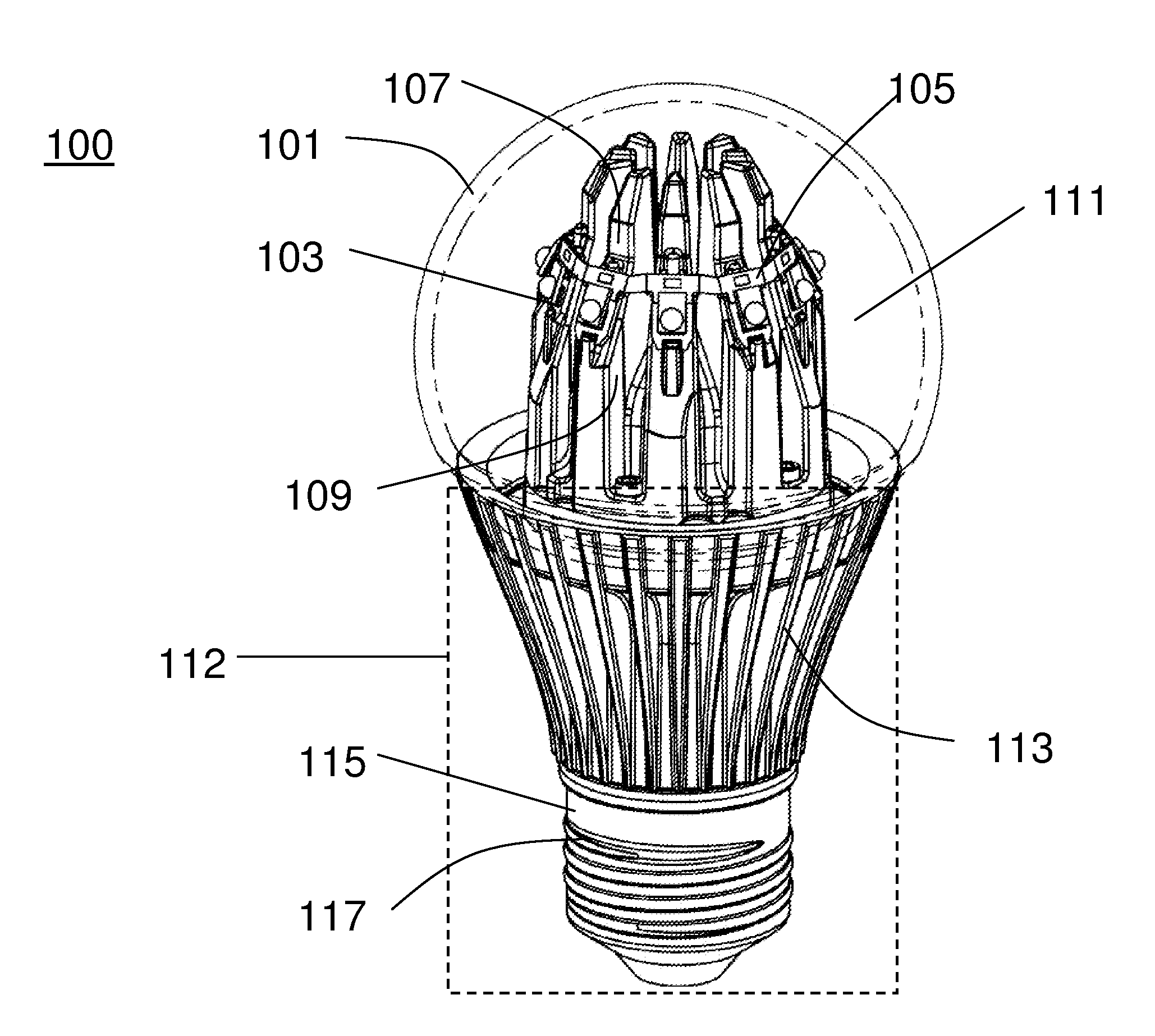
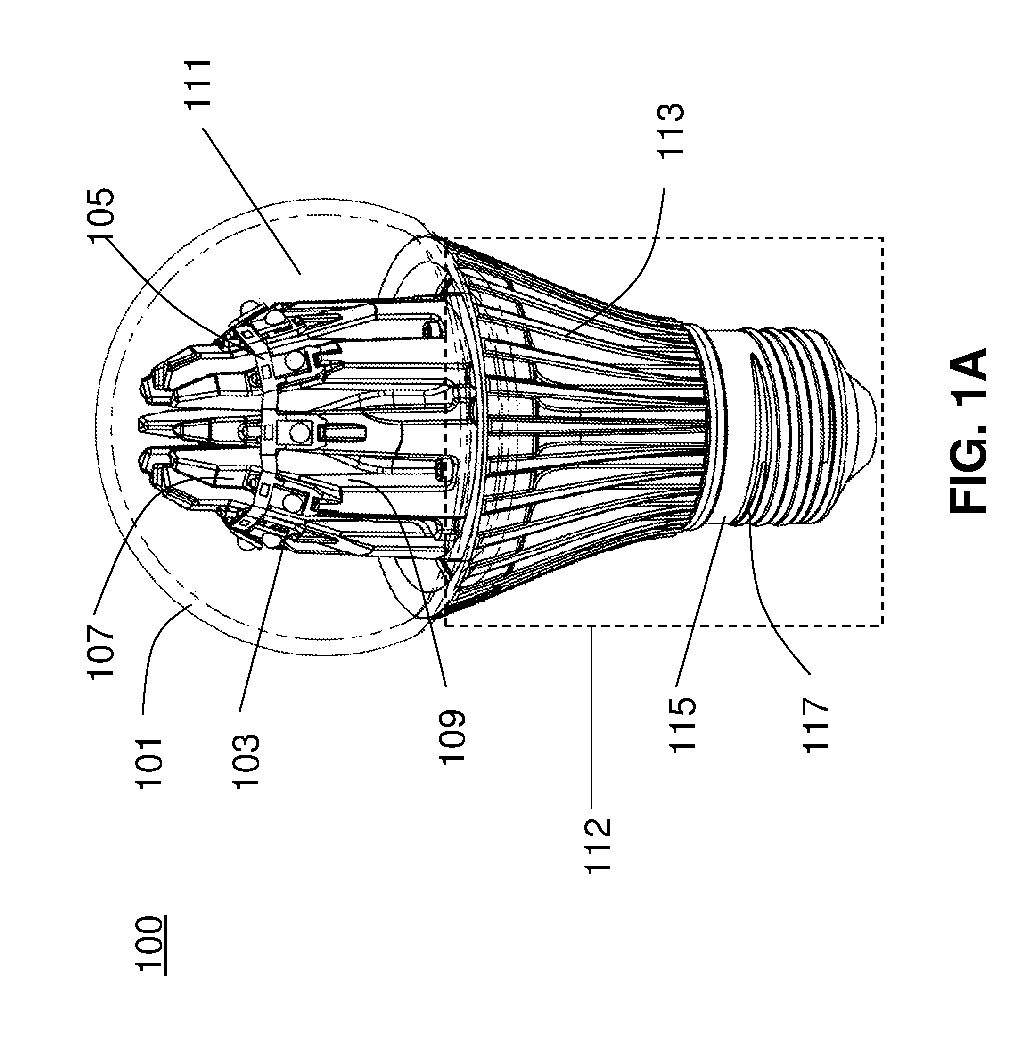
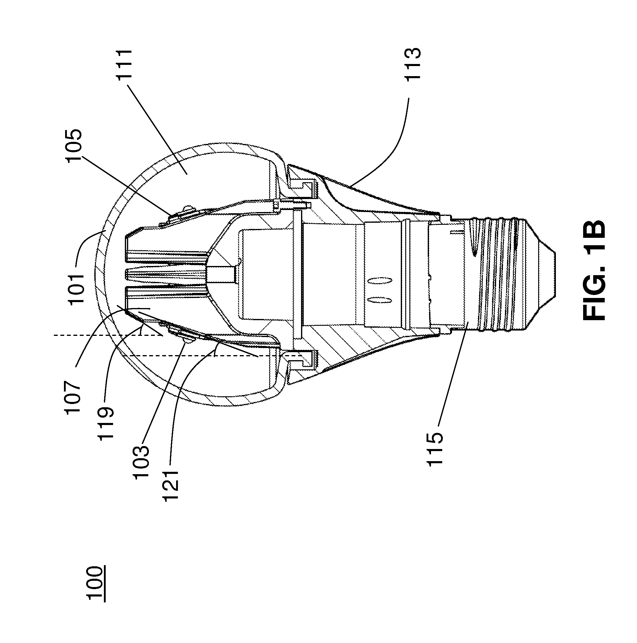
[0017]Various embodiments are described below, relating to LED bulbs. As used herein, an “LED bulb” refers to any light-generating device (e.g., a lamp) in which at least one LED is used to generate the light. Thus, as used herein, an “LED bulb” does not include a light-generating device in which a filament is used to g...


PUM

PropertyMeasurementUnit
temperaturesaaaaaaaaaa
angleaaaaaaaaaa

Abstract

An LED bulb includes a base, a shell connected to the base, and a thermally conducting liquid held within the shell. The LED bulb has a plurality of finger-shaped projections, disposed within the shell. The finger-shaped projections are separated by a plurality of channels formed between pairs of the plurality of finger-shaped projections for holding a plurality of LEDs. The plurality of finger-shaped projections and the plurality of channels are configured to facilitate a passive convective flow of the thermally conductive liquid through the plurality of channels, when the LED bulb is oriented in at least three different orientations. In a first orientation, the shell is disposed vertically above the base. In a second orientation, the shell is disposed on the same horizontal plane as the base. In a third orientation, the shell is disposed vertically below the base.

Description

BACKGROUND[0001]1. Field[0002]The present disclosure relates generally to light emitting-diode (LED) bulbs, and more particularly, to the efficient transfer of heat generated by LEDs in a liquid-filled LED bulb.[0003]2. Related Art[0004]Traditionally, lighting has been generated using fluorescent and incandescent light bulbs. While both types of light bulbs have been reliably used, each suffers from certain drawbacks. For instance, incandescent bulbs tend to be inefficient, using only 2-3% of their power to produce light, while the remaining 97-98% of their power is lost as heat. Fluorescent bulbs, while more efficient than incandescent bulbs, do not produce the same warm light as that generated by incandescent bulbs. Additionally, there are health and environmental concerns regarding the mercury contained in fluorescent bulbs.[0005]Thus, an alternative light source is desired. One such alternative is a bulb utilizing an LED. An LED comprises a semiconductor junction that emits ligh...

Claims


Application Information

Patent Timeline
Patent Type & Authority Applications(United States)
IPC IPC(8): F21V33/00H05K13/00
CPCF21K9/135F21V3/00F21V29/004F21Y2101/02Y10T29/49002F21V3/0436F21V29/506F21V29/58F21V29/83F21V3/0418F21K9/232F21Y2115/10F21V3/062F21V3/061F21S4/00F21V29/71
Inventor WHEELOCK, GLENNHORN, DAVID
Owner SWITCH BULB CO INC
Why Eureka
Try Eureka