Low stray light beam dump with fiber delivery

Active Publication Date: 2012-02-02
KLA TENCOR CORP
View PDF11 Cites 19 Cited by
  • Summary
  • Abstract
  • Description
  • Claims
  • Application Information

AI Technical Summary

Benefits of technology

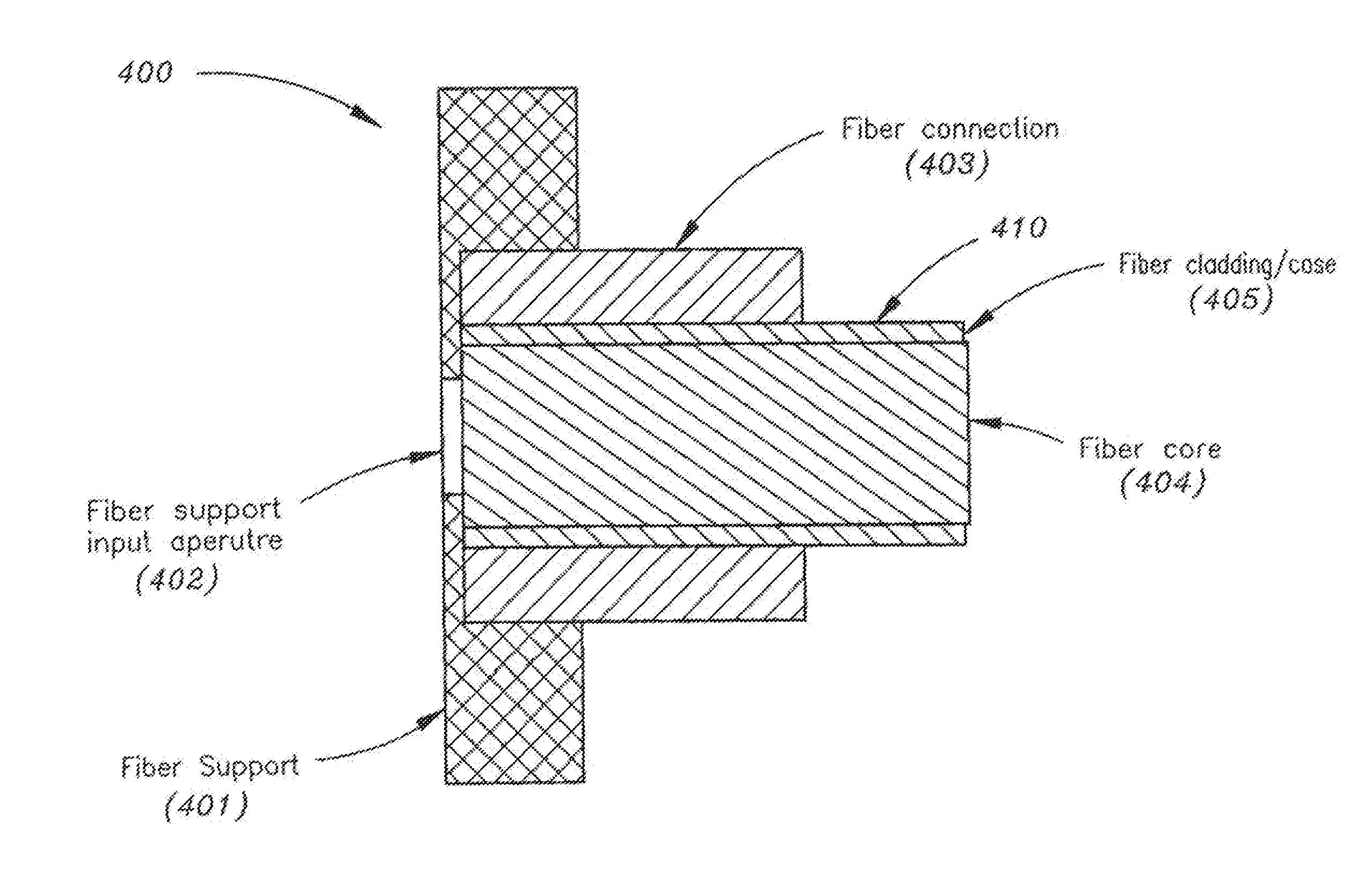
[0005]Accordingly an embodiment of the invention is directed to a beam dump, including: an enclosure, the enclosure configured for being connected to at least one optical fiber, the enclosure configured with an aperture (ex.—the aperture area may be less than 1/1000 of a surface area of the enclosure) for receiving light into an interior of the enclosure via at least one optical fiber, said light being transmitted from a remotely-located light source into the enclosure via the at least one optical fiber, wherein the enclosure is configured for at least substantially containing the received light within the enclosure. The received light may impinge on an internal surf

Problems solved by technology

These currently implemented laser systems may experience problems such as: excess generated heat, excess s

Method used


Image

  • Low stray light beam dump with fiber delivery
  • Low stray light beam dump with fiber delivery
  • Low stray light beam dump with fiber delivery

Examples


Embodiment Construction

[0021]Reference will now be made in detail to the presently preferred embodiments of the invention, examples of which are illustrated in the accompanying drawings.

[0022]The demands of the semiconductor industry for wafer and photomask inspection systems exhibiting high throughput and improvements in resolution are ongoing. Successive generations of such inspection systems tend to achieve higher resolution by illuminating the wafer or reticle using light energy having high power (ex.—deep ultraviolet (DUV) light energy). The primary method to provide adequate DUV power entails generating shorter wavelength light from longer wavelength light. This process of changing wavelengths is commonly called frequency conversion. Frequency conversion requires high peak power light and / or high average power light in order to produce a nonlinear response in an optical crystal. The original light is typically called fundamental light.

[0023]Controlling the light within the frequency conversion syste...


PUM


Abstract

The present invention is directed to a beam dump which is configured for not increasing a temperature of a laser with which it may be implemented. The beam dump may include an opaque enclosure which is configured for receiving light (ex.—initial light) from a light source (ex.—a frequency-converted laser), said light being delivered through an aperture of the enclosure via one or more connected optical fibers. The received light may be scattered within the enclosure. However, the beam dump is configured for minimizing the amount of light which is back scattered light into the fiber(s). For instance, the amount of back scattered light may be less than 1/1000 of the initial light. Further, the beam dump may be configured for minimizing photocontamination which may be caused when the light contacts interior surfaces of the enclosure. Still further, the beam dump may be a small size, low cost structure.

Description

CROSS-REFERENCE TO RELATED APPLICATIONS[0001]The present application claims priority under 35 U.S.C. §119(e) to U.S. Provisional Application No. 61 / 369,591 entitled: Low Stray Light Beam Dump with Fiber Delivery filed Jul. 30, 2010, which is hereby incorporated by reference in its entirety.FIELD OF THE INVENTION[0002]The present invention generally relates to illuminators used in conjunction with inspection systems, such as semiconductor wafer inspection systems and photomask inspection systems, and more particularly to a frequency converted light source for use with such inspection systems.BACKGROUND OF THE INVENTION[0003]Currently available illuminators (ex.—laser systems; lasers) utilized in conjunction with inspection systems (ex.—semiconductor wafer inspection systems and photomask inspection systems) typically handle residual light from frequency conversion processes by sending the residual light into an absorbing medium or beam dump. These currently implemented laser systems ...

Claims


Application Information

Patent Timeline
IPC IPC(8): G02B6/02H01S3/00
CPCG02B6/243
Inventor ARMSTRONG, J. JOSEPH
Owner KLA TENCOR CORP
Why Eureka
Try Eureka