
Cable assembly

a technology of cable assembly and cable, which is applied in the direction of coupling device connection, coupling protective earth/shielding arrangement, four or more pole connection, etc., and can solve problems such as weakening the function of preventing emi

Active Publication Date: 2012-02-02
HON HAI PRECISION IND CO LTD
View PDF15 Cites 33 Cited by
  • Summary
  • Abstract
  • Description
  • Claims
  • Application Information

AI Technical Summary

Benefits of technology

[0005]Accordingly, an object of the present invention is to provide a cable assembly prevented form EMI.

Problems solved by technology

A junction line is formed between the first metal shell and the second metal shell, and the junction may be split during in the using time, thus, the function preventing EMI can be weaken.

Method used


Image

  • Cable assembly
  • Cable assembly
  • Cable assembly

Examples


Embodiment Construction

[0014]Reference will now be made to the drawing figures to describe the present invention in detail.

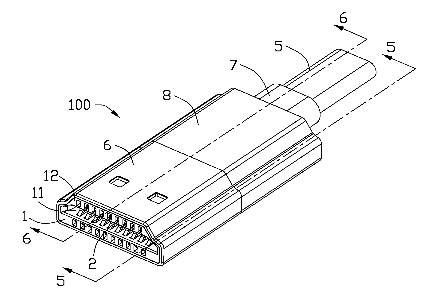
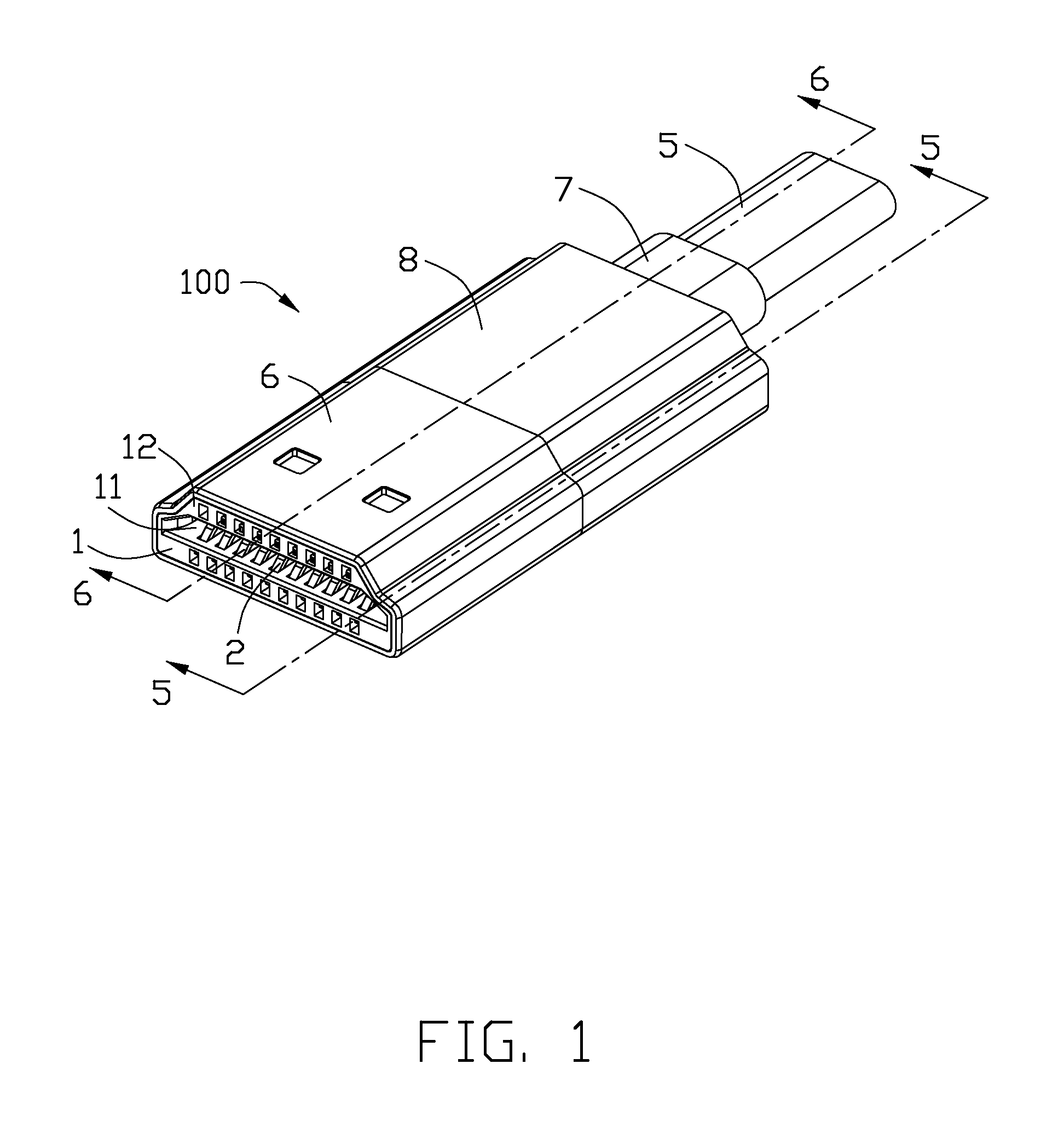
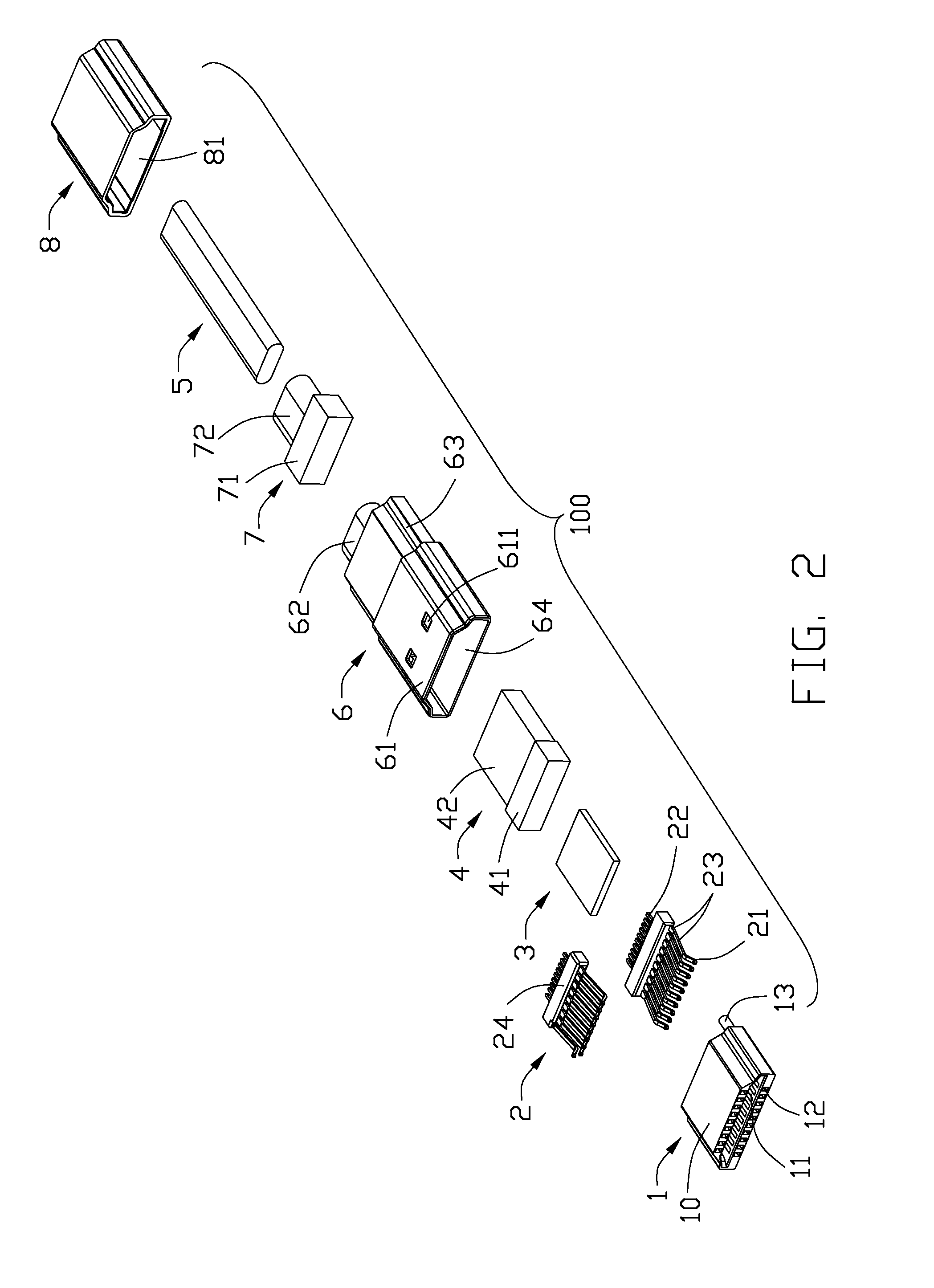
[0015]Referring to FIGS. 1 to 6, a cable assembly 100 in accordance with the present invention comprises a housing 1, a plurality of conductive terminals 2 received in the housing 1, a printed circuit board (PCB) 3 assembled on the rear end of conductive terminals 2, an inner molding 4 enclosing the printed circuit board 3, a cable 5 having a plurality of wires (not shown), a metal shell 6 enclosing the housing 1, a strain relief portion 7 and a rear cover 8 assembled on the metal shell 6.

[0016]The housing 1 comprises a main portion 10, a pair of cylinders 13 extending rearwardly from the rear surface of the main portion 10 and a receiving slit 14 recessing forwardly from the rear surface of the main portion 10. The main portion 10 comprises a trapeziform receiving plug space 11 with four walls for connecting to a complementary connector (not shown) and a plurality of terminal slits 1...


PUM


Abstract

A cable assembly, comprising a housing having a main portion, a plurality of conductive terminals received in the main portion of the housing, a cable having a plurality of wires and a metal shell with a no-joint-line surface enclosing the housing and comprising a front portion enclosing the housing and a rear portion enclosing the cable and a receiving space passing through the front portion and the rear portion.

Description

FIELD OF THE INVENTION[0001]The present invention relates to a cable assembly, and more particularly to a cable assembly having a metal shell for preventing EMI.DESCRIPTION OF PRIOR ART[0002]Recently, a cable assembly always includes a metal shell, an insulative housing received in the metal shell, a plurality of conductive terminals received in the insulative housing, a number of cables electrically connected to the conductive terminals and a cover mold on and enclosing the outer of the metal shell and the cable.[0003]For the improvement of the technical requirement, many technical solutions have been proposed. E.g. How to improve the function of prevention EMI for cable assembly. CN Pat. No. CN201081834Y, issued on Jul. 2, 2008, disclosed a cable assembly including an insulative main housing having a mating interface, a plurality of terminals located in the insulative main housing and exposed out of the mating interface, a first metal shell, a second metal shell and an insulative ...

Claims


Application Information

Patent Timeline
Patent Type & Authority Applications(United States)
IPC IPC(8): H01R13/648H01R13/58
CPCH01R9/03H01R13/405H01R13/5804H01R13/6593H01R2107/00H01R13/6461H01R13/5845
Inventor SU, PING-SHENGLI, XIAO-LI
Owner HON HAI PRECISION IND CO LTD
Learn More