Propeller shaft

a technology of shaft and shaft shaft, applied in the direction of shaft and bearing, clutch, yielding coupling, etc., can solve the problems of increasing cost, insufficient effect of suppressing the occurrence of stick-slip,

Active Publication Date: 2012-02-02
JTEKT CORP
View PDF4 Cites 17 Cited by
  • Summary
  • Abstract
  • Description
  • Claims
  • Application Information

AI Technical Summary

Benefits of technology

[0029]FIG. 10 is a graph showing the results of observation on the effect of suppressing occurrence of stick-slip in the propeller shaft according to the embodiment of the invention.

Problems solved by technology

However, the sufficient effect of suppressing occurrence of stick-slip is not obtained.
In this case, however, the cost increases.

Method used


Image

  • Propeller shaft
  • Propeller shaft
  • Propeller shaft

Examples


Embodiment Construction

[0030]Hereafter, a propeller shaft according to an embodiment of the invention will be described in detail with reference to the accompanying drawings.

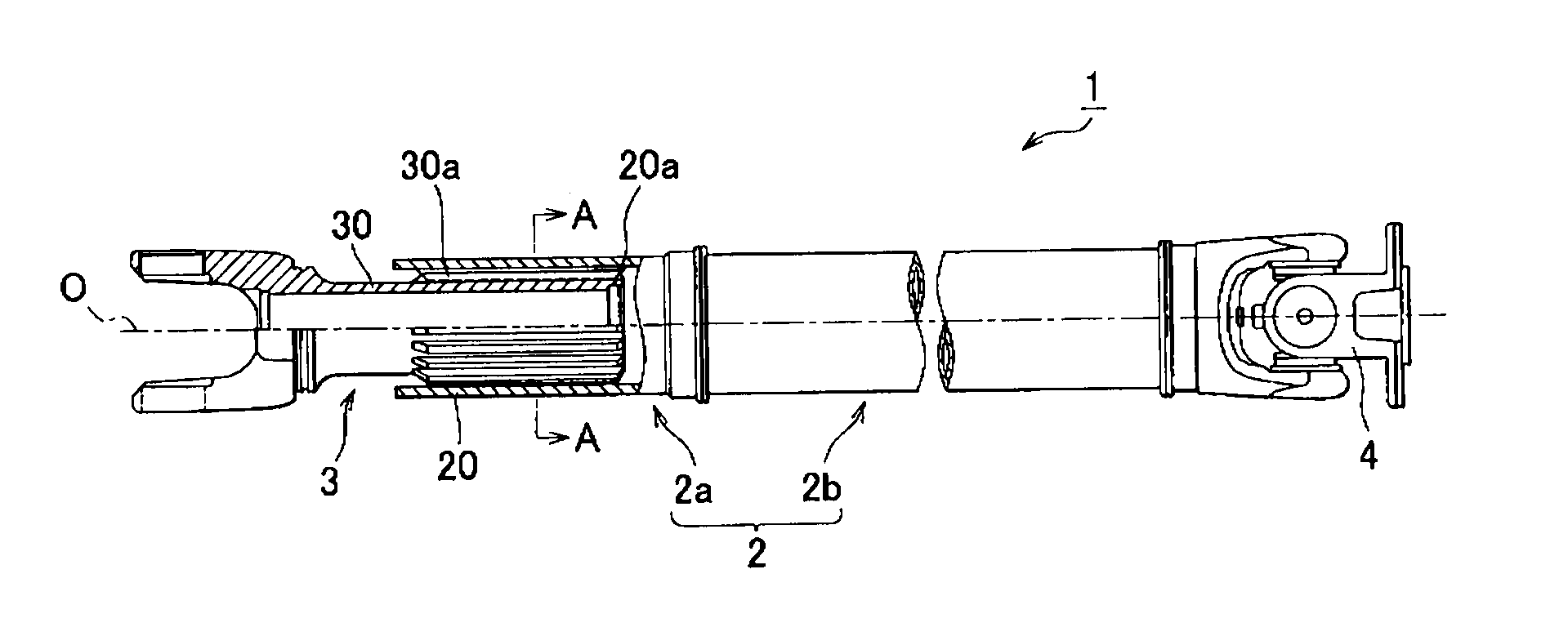
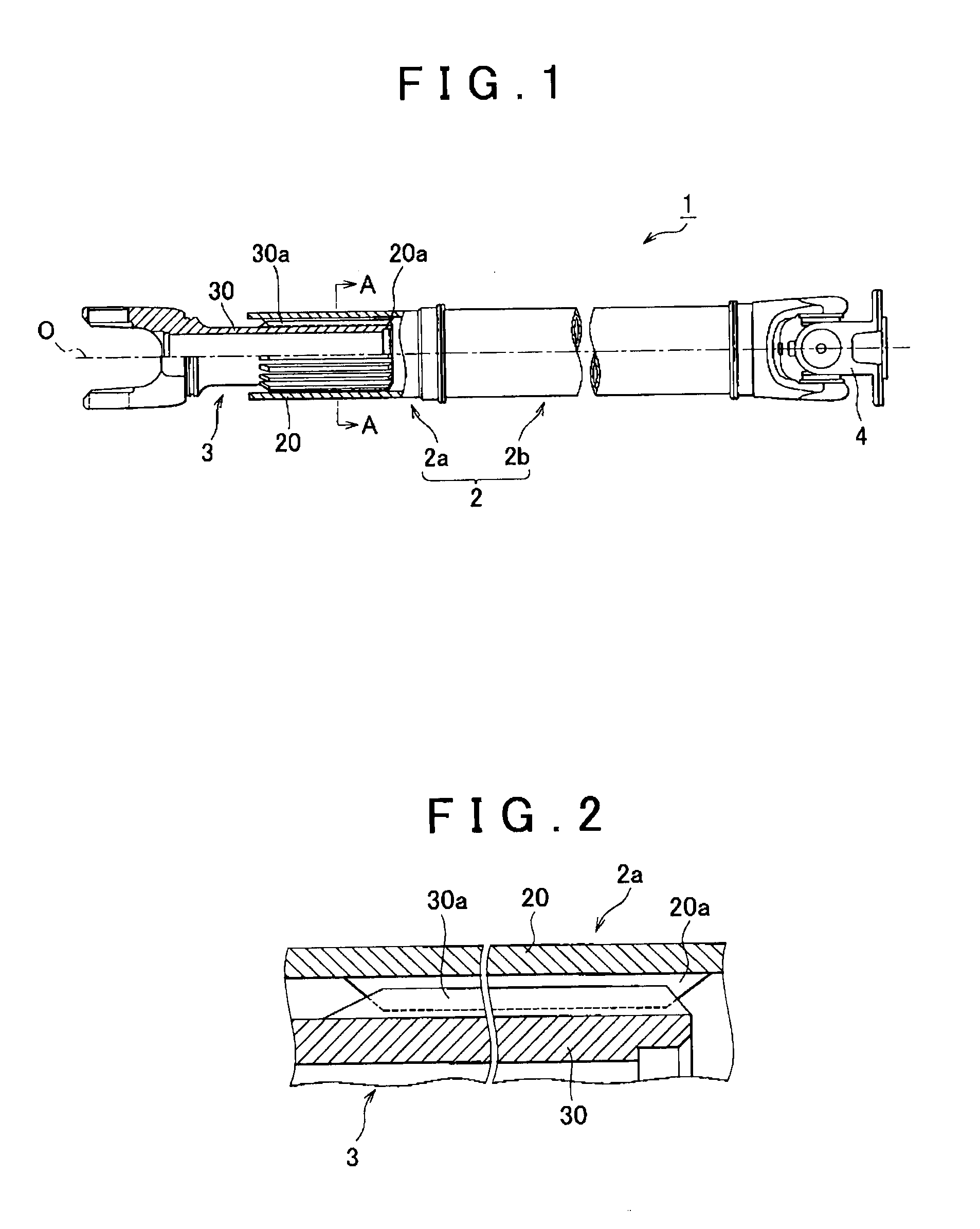
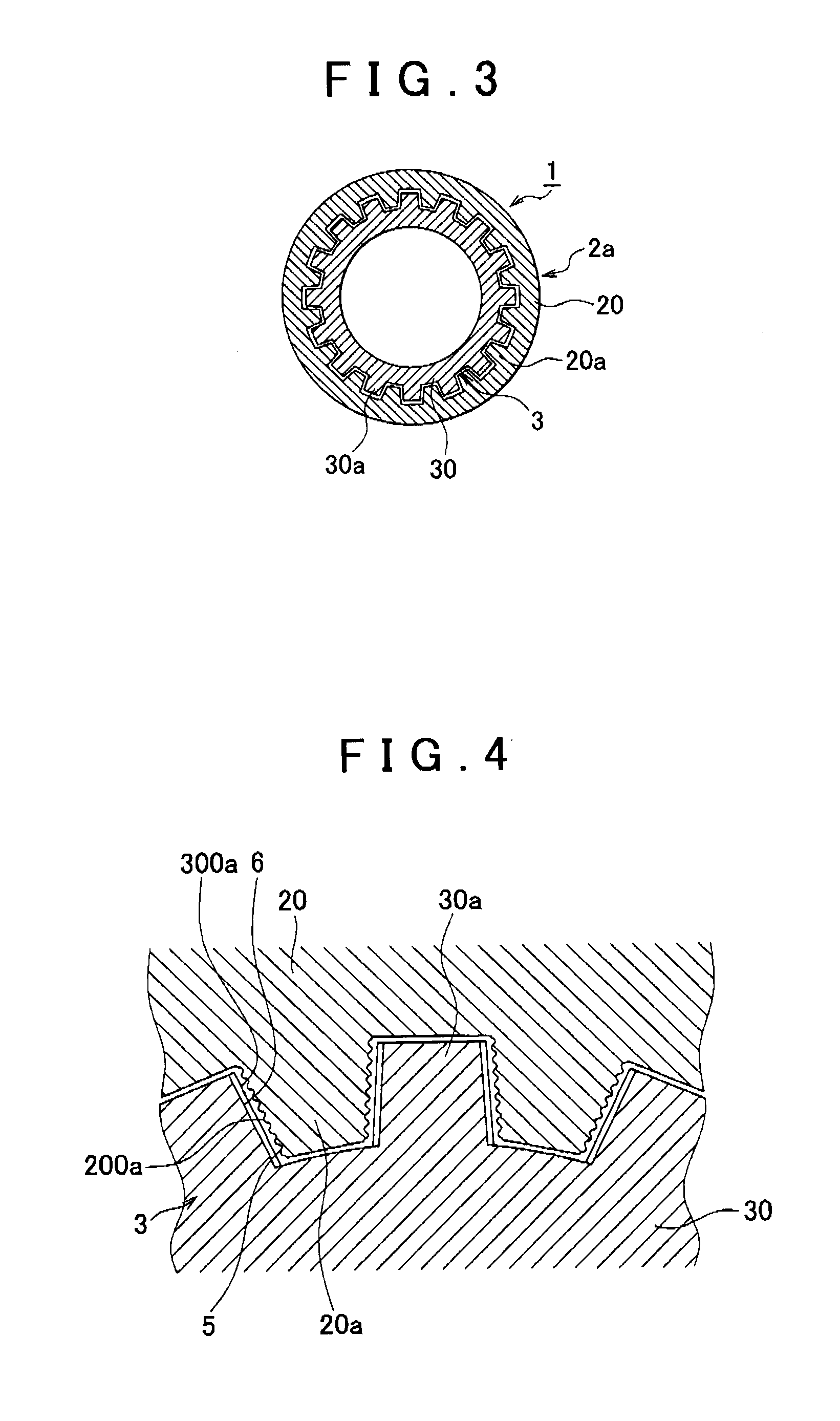
[0031]The overall structure of a propeller shaft 1 for a vehicle will be described. FIG. 1 shows the entirety of the propeller shaft 1. FIGS. 2 and 3 show a spline-engagement state of the propeller shaft 1. As shown in FIGS. 1 to 3, the propeller shaft 1 includes a first shaft 2 and a second shaft 3, and is interposed between a transmission (not shown) and a differential gear (not shown). The propeller shaft 1 is structured so as to transmit a driving force from an engine to the differential gear via the transmission.

[0032]A bellow seal member (not shown) is stretchably fitted to the propeller shaft 1. The seal member is made of, for example, rubber, and used to provide sealing between an inner periphery spline portion (spline portion 20 described later) and an outer periphery spline portion (spline portion 30 described later). Grease...


PUM


Abstract

A propeller shaft includes a first shaft and a second shaft. The first shaft has a torque transmission face in which a plurality of fine grooves extending in a first direction (face width direction) is formed. The second spline shaft is coupled to the first spline shaft so as to be movable relative to the first spline shaft in the axial direction of the first spline shaft, and has a torque transmission face in which a plurality of second fine grooves extending in a second direction that crosses the first direction is formed.

Description

INCORPORATION BY REFERENCE[0001]The disclosure of Japanese Patent Application No. 2010-168394 filed on Jul. 27, 2010 including the specification, drawings and abstract is incorporated herein by reference in its entirety.BACKGROUND OF THE INVENTION[0002]1. Field of the Invention[0003]The invention relates to a propeller shaft that includes an input shaft and an output shaft.[0004]2. Description of Related Art[0005]For example, Japanese Patent Application Publication No. 6-173934 (JP 6-173934 A) describes a conventional propeller shaft that includes an input shaft and an output shaft, and that is interposed between a transmission and a differential gear to transmit an output from the transmission to the differential gear.[0006]The input shaft has a cylindrical portion, and is coupled to an output portion of the transmission via a first joint portion.[0007]The output shaft is connected to the input shaft via a telescopic portion, and is also coupled to an input portion of the different...

Claims


Application Information

Patent Timeline
Patent Type & Authority Applications(United States)
IPC IPC(8): F16C3/03
CPCF16D1/101F16D3/06F16D2300/10F16D2001/103F16D3/18F16D2300/06
Inventor ANDO, JUNJISUZUKI, TOMOOOGAWA, TOMOKI
Owner JTEKT CORP
Why Eureka
Try Eureka