System and method for presenting information representative of lesion formation in tissue during an ablation procedure

Active Publication Date: 2012-02-02
ST JUDE MEDICAL ATRIAL FIBRILLATION DIV
View PDF6 Cites 149 Cited by
  • Summary
  • Abstract
  • Description
  • Claims
  • Application Information

AI Technical Summary

Benefits of technology

[0010]The present invention is directed to a system and method for presenting information representative of lesion formation in tissue during an ablation procedure. The system, in accordance with present teachings, comprises an electronic control unit (ECU). The ECU is configured to acquire a value for at least one of an ablation description parameter and a position signal metric, wherein the value corresponds to a location in the tissue. The ECU is further configured to evaluate the acquired

Problems solved by technology

Atrial arrhythmias can create a variety of dangerous conditions including irregular heart rates, loss of synchronous atrioventricular contractions and stasis of blood flow which can lead to a variety of ailments and even death.
One challenge with ablation procedures is in the assessment of the integrity or efficacy of the lesion formed during the ablation procedure.
Conventional techniques such as these suffer from a number of drawbacks, however.
For example, oftentimes ablation description parameters that the clinician monitors are displayed on display monitors of different devices, thereby rendering the monitoring difficult and the interpretation prone to error.
Further, many parameters are contaminated with RF, cardiac motion, or respiratory motion artifacts, thereby contaminating the signals, which can lead to errors in both lesion marker location and lesion quality estimation.
Additionally, respiratory artifacts and ablation generator (RF) impedance can lead to unreliable m

Method used


Image

  • System and method for presenting information representative of lesion formation in tissue during an ablation procedure
  • System and method for presenting information representative of lesion formation in tissue during an ablation procedure
  • System and method for presenting information representative of lesion formation in tissue during an ablation procedure

Examples


Embodiment Construction

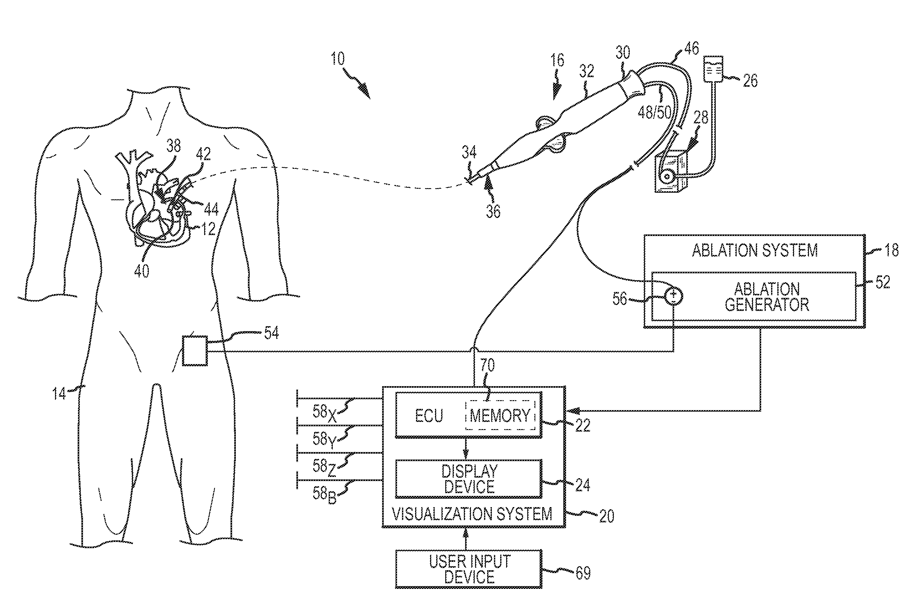
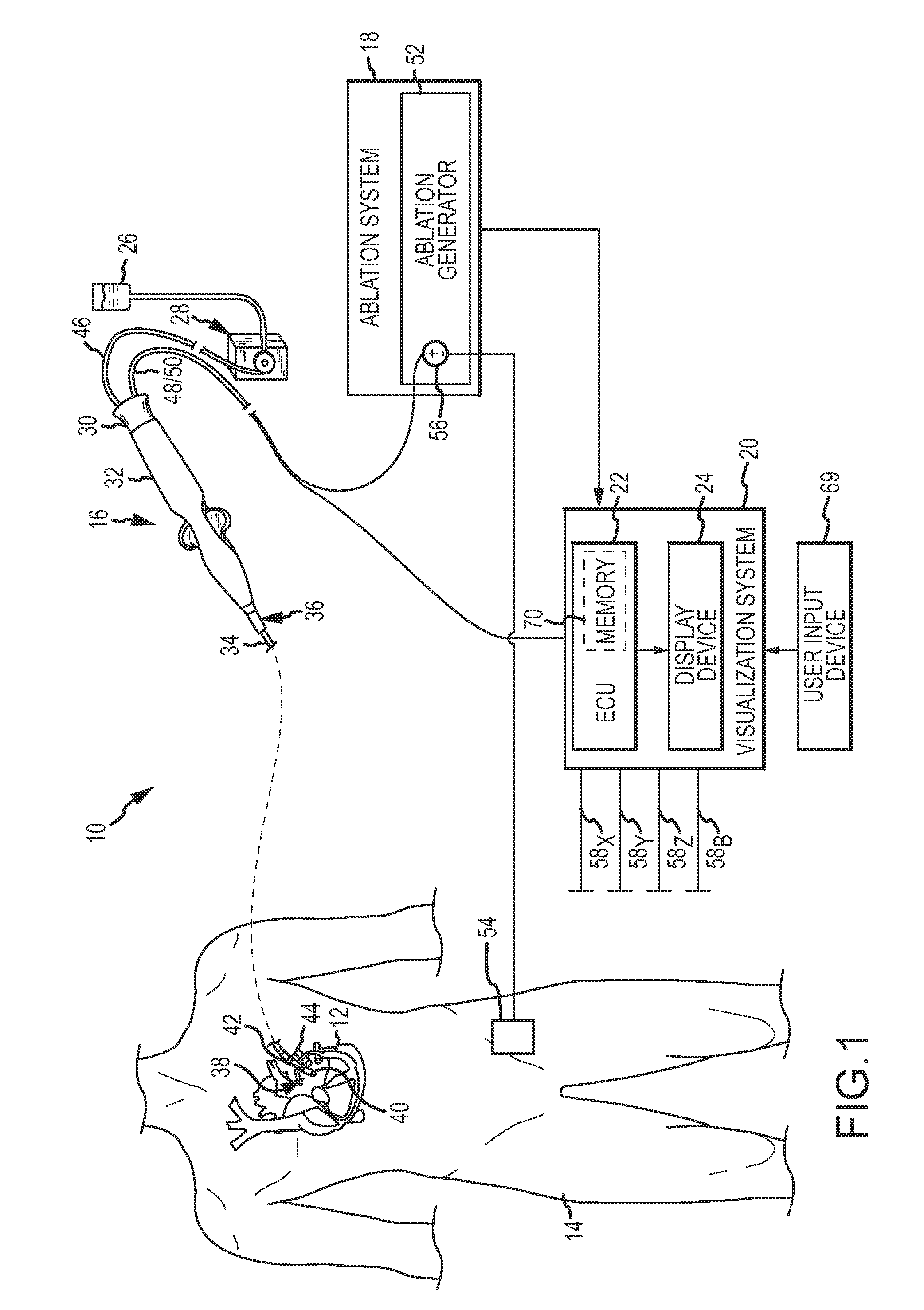
[0028]Referring now to the drawings wherein like reference numerals are used to identify identical components in the various views, FIG. 1 illustrates one exemplary embodiment of a system 10 for performing one more diagnostic and / or therapeutic functions that includes components for presenting information representative of lesion formation in a tissue 12 of a body 14 during an ablation procedure performed thereon. In an exemplary embodiment, the tissue 12 comprises heart or cardiac tissue within a human body 14. It should be understood, however, that the system 10 may find application in connection with the ablation of a variety of other tissues within human and non-human bodies.

[0029]Among other components, the system 10 includes a medical device (such as, for example, a catheter 16) an ablation system 18, and a system 20 for the visualization, navigation, and / or mapping of internal body structures. The system 20 may include, for example and without limitation, an electronic contro...


PUM


Abstract

A method and system for presenting information representative of lesion formation is provided. The system comprises an electronic control unit (ECU). The ECU is configured to acquire a value for an ablation description parameter and/or a position signal metric, wherein the value corresponds to a location in the tissue. The ECU is further configured to evaluate the value, assign it a visual indicator of a visualization scheme associated with the parameter/metric corresponding to the value, and generate a marker comprising the visual indicator such that the marker is indicative of the acquired value. The method comprises acquiring a value for the parameter/metric, and evaluating the value. The method further includes assigning a visual indicator of a visualization scheme associated with the parameter/metric corresponding to the value, and generating a marker comprising the visual indicator.

Description

CROSS REFERENCE TO RELATED APPLICATIONS[0001]This application is a continuation-in-part of U.S. patent application Ser. No. 12 / 946,941 entitled “System and Method for Assessing the Formation of a Lesion in Tissue” filed Nov. 16, 2010 and currently pending, which, in turn, is a continuation-in-part of U.S. patent application Ser. No. 12 / 622,488 entitled “System and Method for Assessing Lesions in Tissue” filed Nov. 20, 2009 and currently pending, which, turn, claimed the benefit of U.S. Provisional Application Ser. No. 61 / 177,876 entitled “System and Method for Assessing Lesions in Tissue” filed May 13, 2009 and now expired. The entire disclosures of each of the above identified applications are incorporated herein by reference.BACKGROUND OF THE INVENTION[0002]a. Field of the Invention[0003]This disclosure relates to a system and method for presenting information representative of lesion formation in tissue during an ablation procedure. More particularly, this disclosure relates to a...

Claims


Application Information

Patent Timeline
IPC IPC(8): A61B18/14A61B18/12
CPCA61B5/0402A61B2218/002A61B18/1233A61B18/14A61B18/1492A61B18/24A61B19/56A61B2017/00128A61B2018/00178A61B2018/00351A61B2018/00577A61B2018/00702A61B2018/00714A61B2018/00738A61B2018/00779A61B2018/00875A61B2018/00892A61B2018/0212A61B2018/0262A61B2019/2211A61B2019/465A61B2019/504A61B2019/5246A61B2019/5251A61N7/022A61B5/7203A61B5/042A61B2034/104A61B2034/2046A61B2034/301A61B34/25A61B2090/065A61B2034/2051A61B5/283A61B5/318A61B5/367A61B2034/2072A61B2017/00199A61B2018/00357A61B2018/00648
Inventor AFONSO, VALTINO X.DRAGNEV, LUBOMIR V.CUMMING, SARAH E.SHAI, YITZHAK I.PAUL, SAURAV
Owner ST JUDE MEDICAL ATRIAL FIBRILLATION DIV
Why Eureka
Try Eureka