

Multi-core, multi-blade, and multi-node network environment simulation
a network environment and simulation technology, applied in the field of network work, can solve the problems of not being able to fully simulate a fiber network, unable to fully test a complex embedded software system, and the hardware that the software is supposed to run on is usually not availabl
- Summary
- Abstract
- Description
- Claims
- Application Information
AI Technical Summary
Benefits of technology
Problems solved by technology
Method used
Image

Examples
Embodiment Construction
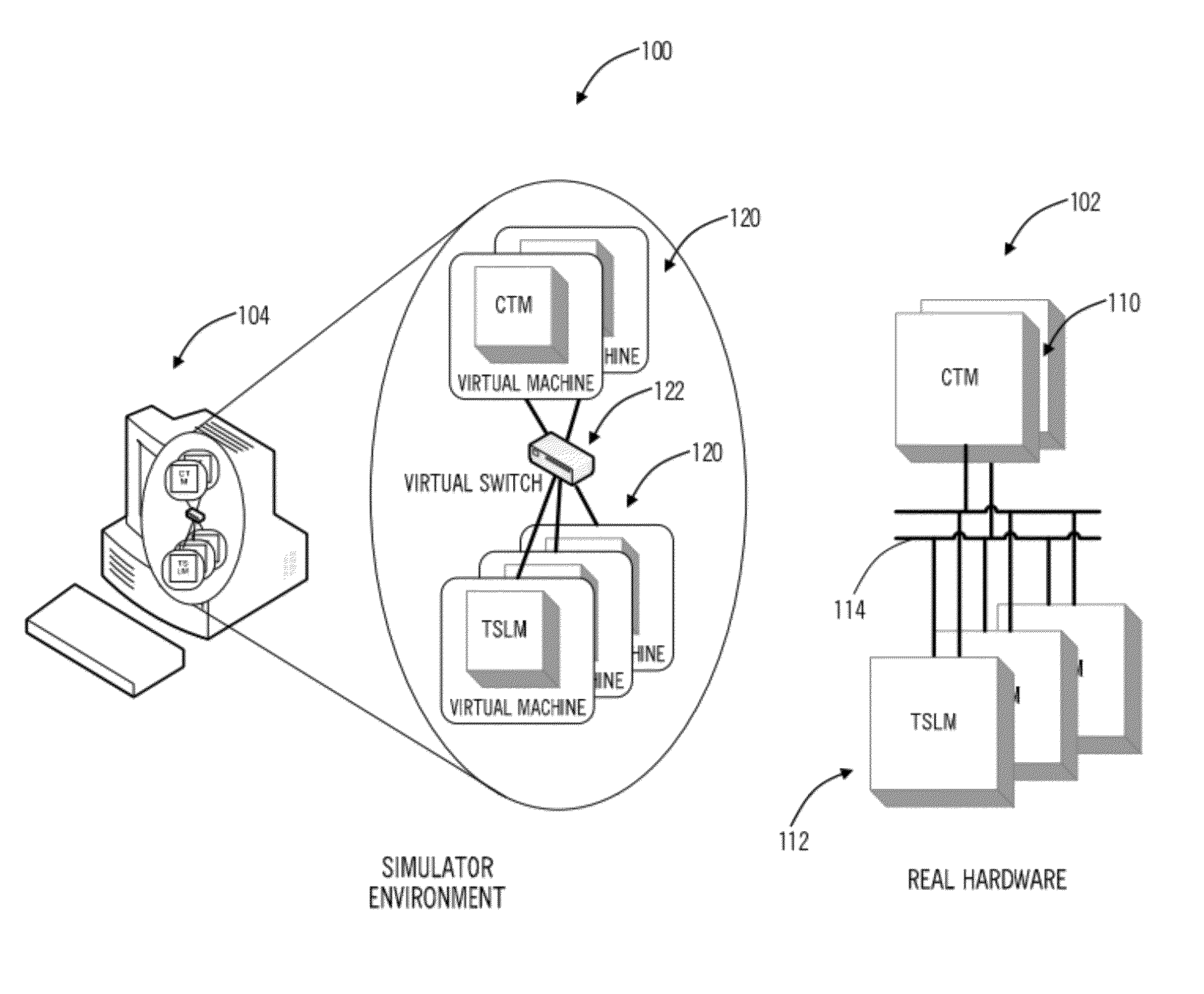
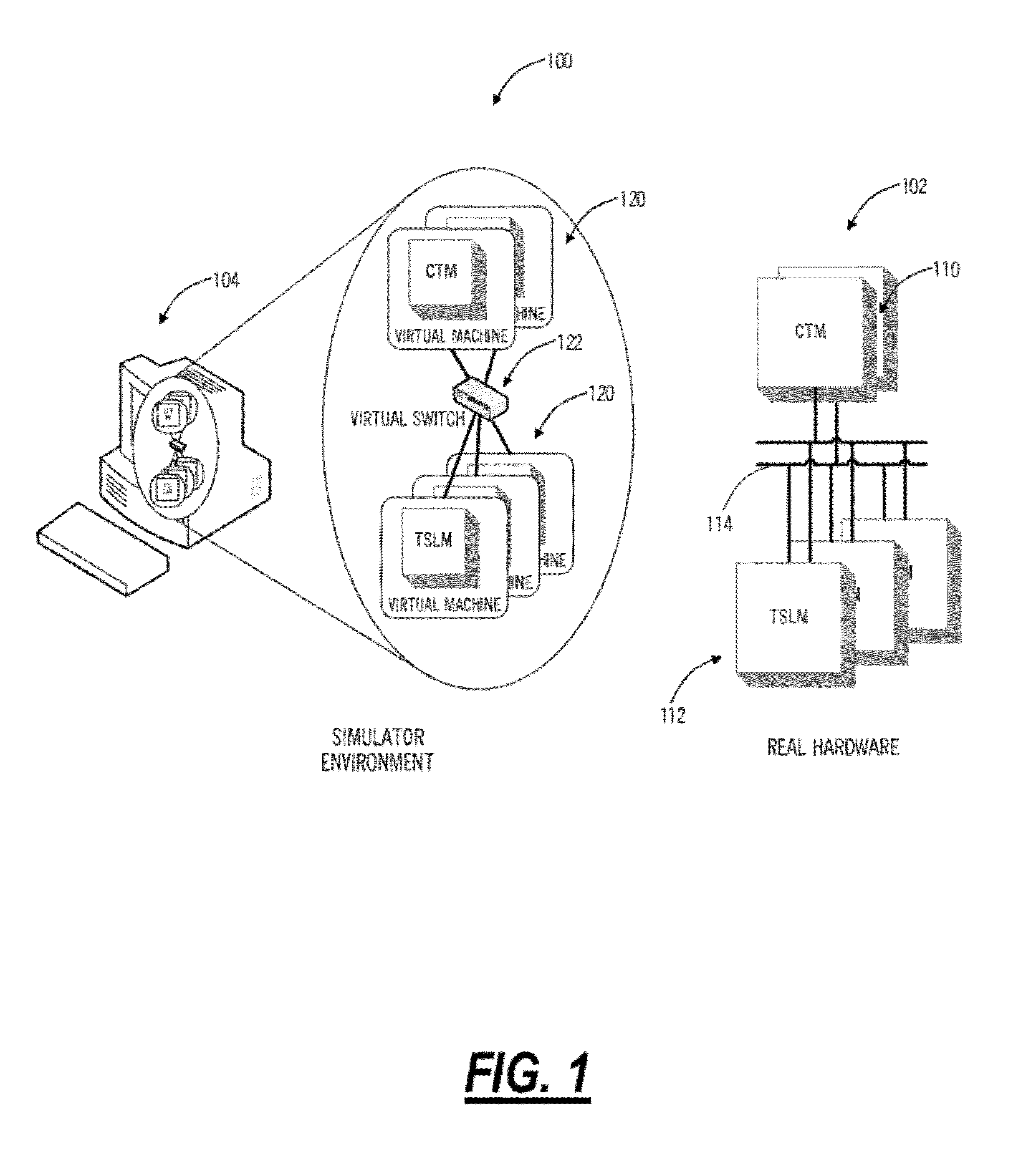
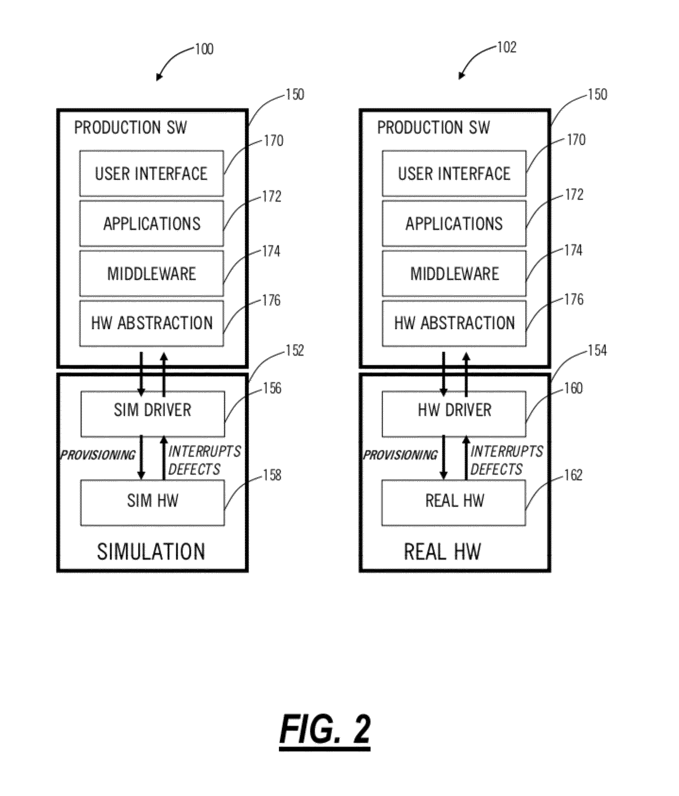
[0015]In various exemplary embodiments, the present invention provides systems and methods for a simulation environment that simulates hardware at a fiber level, a data plane level, a card level, and a chassis level. The simulation environment may be utilized in development and testing of complex, real time, embedded software systems, such as, for example, routers, switches, access devices, base stations, optical switches, optical add / drop multiplexers, DWDM devices, Ethernet switches, Optical Transport Network (OTN) switches, and the like. In an exemplary embodiment, the simulation environment operates on one or more workstations utilizing a virtual machine to operate a virtualized module, line card, line blade, etc. Further, a plurality of virtual machines may operate together to operate a virtualized chassis forming a network element. Advantageously, the present invention provides state of the art data plane traffic and control plane simulation that reduces development time and c...
PUM
 Abstract
Description
Claims
Application Information