

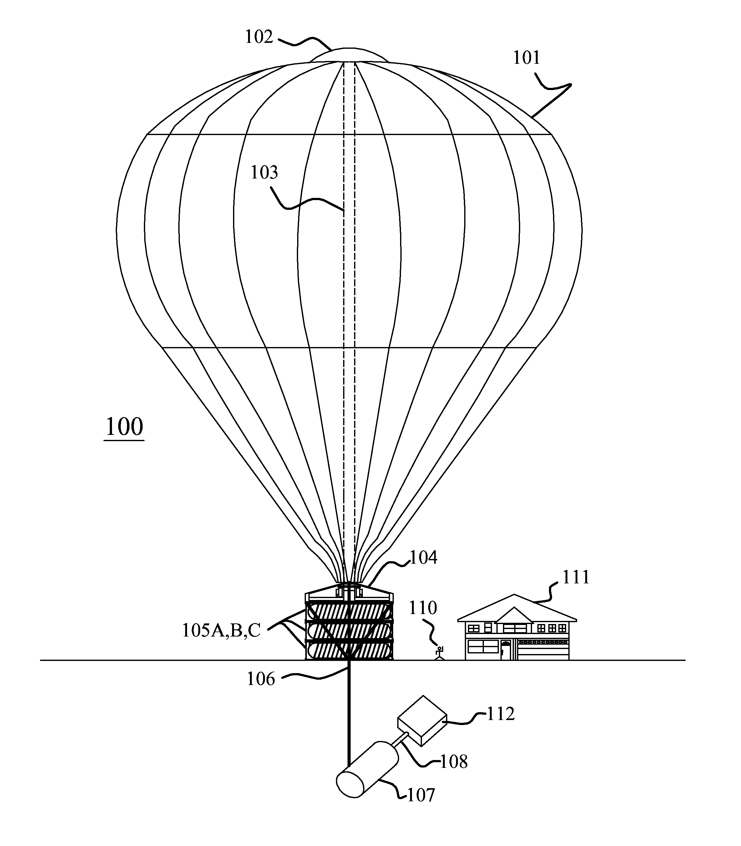
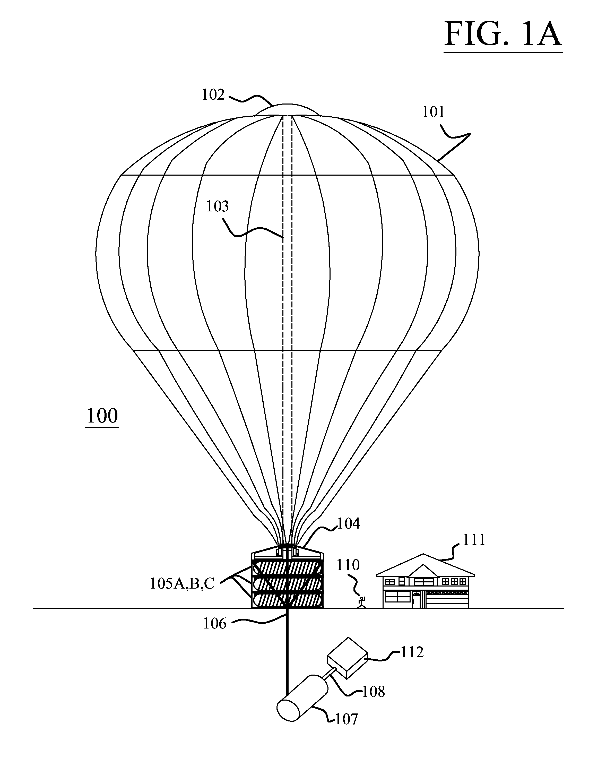
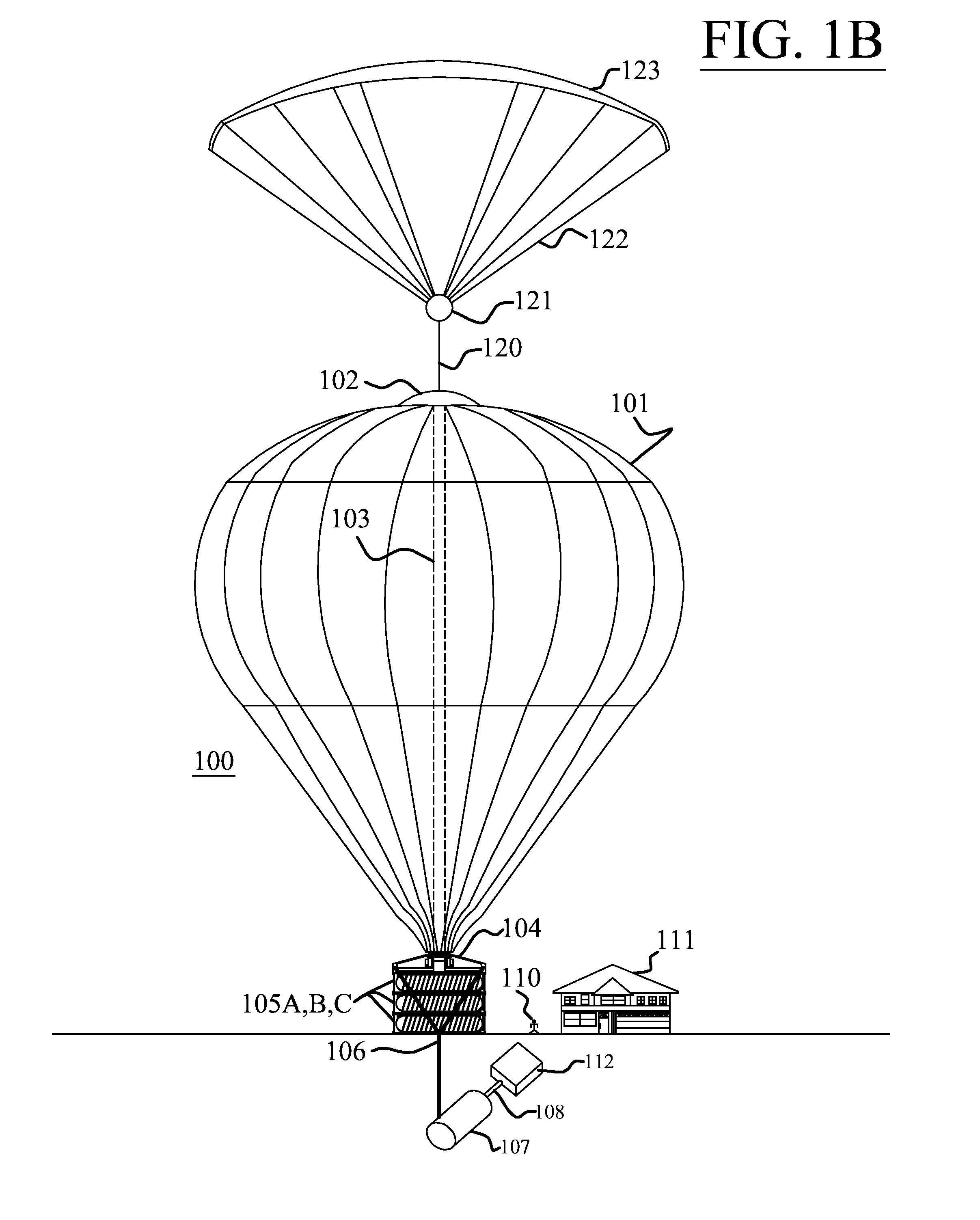
Atmospheric lapse rate cooling system
a cooling system and atmospheric lapse rate technology, applied in the field of cooling systems, can solve the problems of 2.5% of power loss, insignificant current district cooling system, and low cost of pumping, and achieve the effect of increasing altitude or lapse rate, and reducing atmospheric temperatur
- Summary
- Abstract
- Description
- Claims
- Application Information
AI Technical Summary
Benefits of technology
Problems solved by technology
Method used
Image

Examples
embodiments
[0070]In the following description of the following embodiments, reference is made to the accompanying drawings that form a part hereof, and in which is known by way of illustration a specific embodiment in which the invention may be practiced. It is to be understood that other embodiments may be utilized or combinations, thereof, and structural changes may be made without departing from the scope of the present invention.
Overview
[0071]Thermal storage systems have been used for years to store cooling during off peak hour to take advantage of reduced electrical rates and then supply the stored cheaper cooling during peak hours. The high cost of electrical power and the negative impact electricity production and consumption has caused on the planet forced engineers to come up with ways to reduce the cost of cooling and the demand on utilities as cooling loads during peak hours account for a significant draw of electricity. Cooling of buildings in some instances accounts for as much as...
PUM
 Abstract
Description
Claims
Application Information