
Susceptor and apparatus for CVD with the susceptor

Inactive Publication Date: 2012-02-09
SAMSUNG ELECTRONICS CO LTD
View PDF0 Cites 4 Cited by
  • Summary
  • Abstract
  • Description
  • Claims
  • Application Information

AI Technical Summary

Benefits of technology

[0010]According to example embodiments, there may be provided a susceptor for a chemical vapor deposition (CVD) apparatus capable of efficiently positioning a substrate supporting unit, such as a satellite disc, being returned to the susceptor.

Problems solved by technology

However, when the robot arm directly lifts the substrate, the substrate may be damaged due to a sudden temperature change.

Method used


Image

  • Susceptor and apparatus for CVD with the susceptor
  • Susceptor and apparatus for CVD with the susceptor
  • Susceptor and apparatus for CVD with the susceptor

Examples


Embodiment Construction

[0023]Reference will now be made in detail to example embodiments, examples of which are illustrated in the accompanying drawings, wherein like reference numerals refer to the like elements throughout. Example embodiments are described below to explain the present disclosure by referring to the figures.

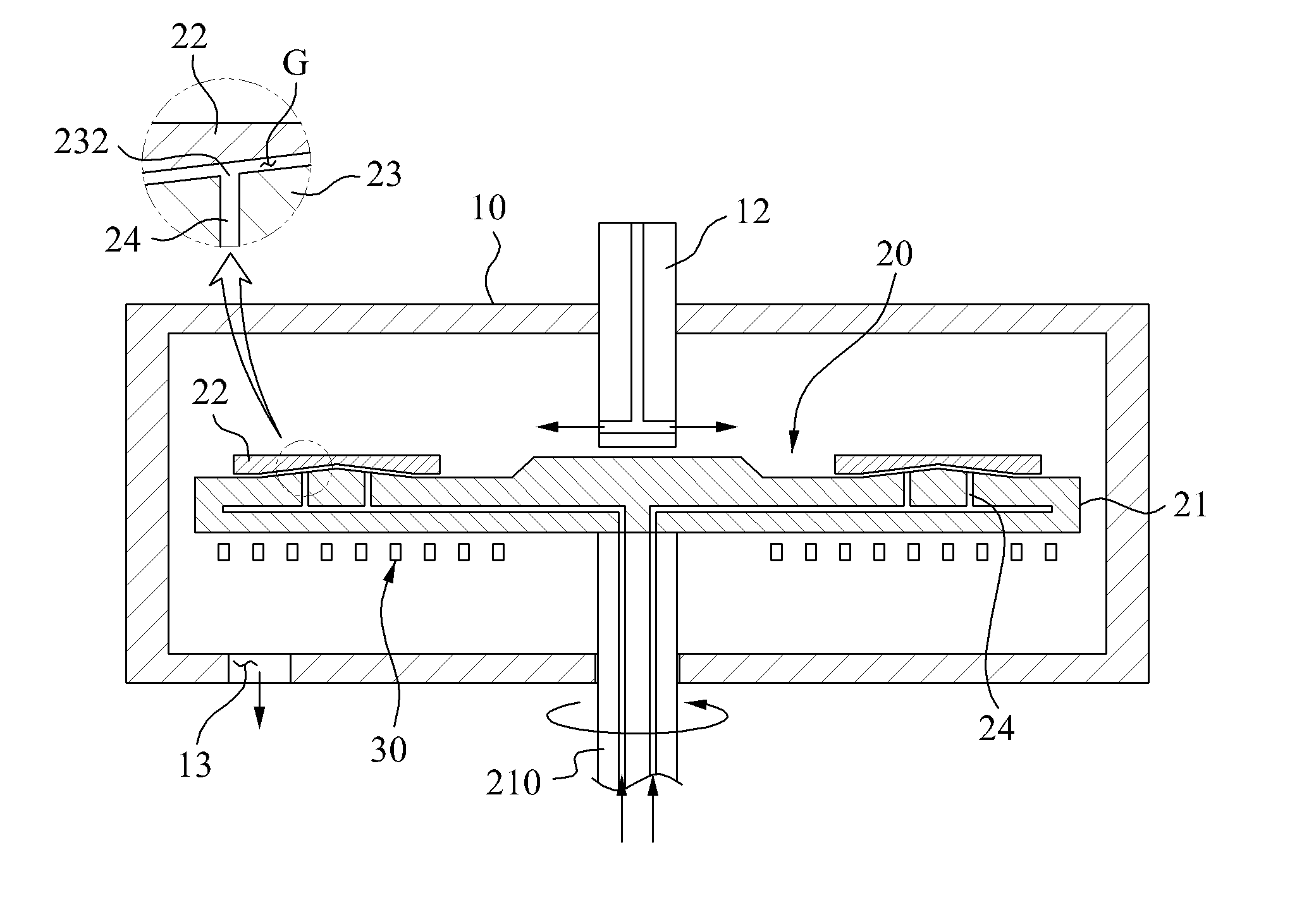
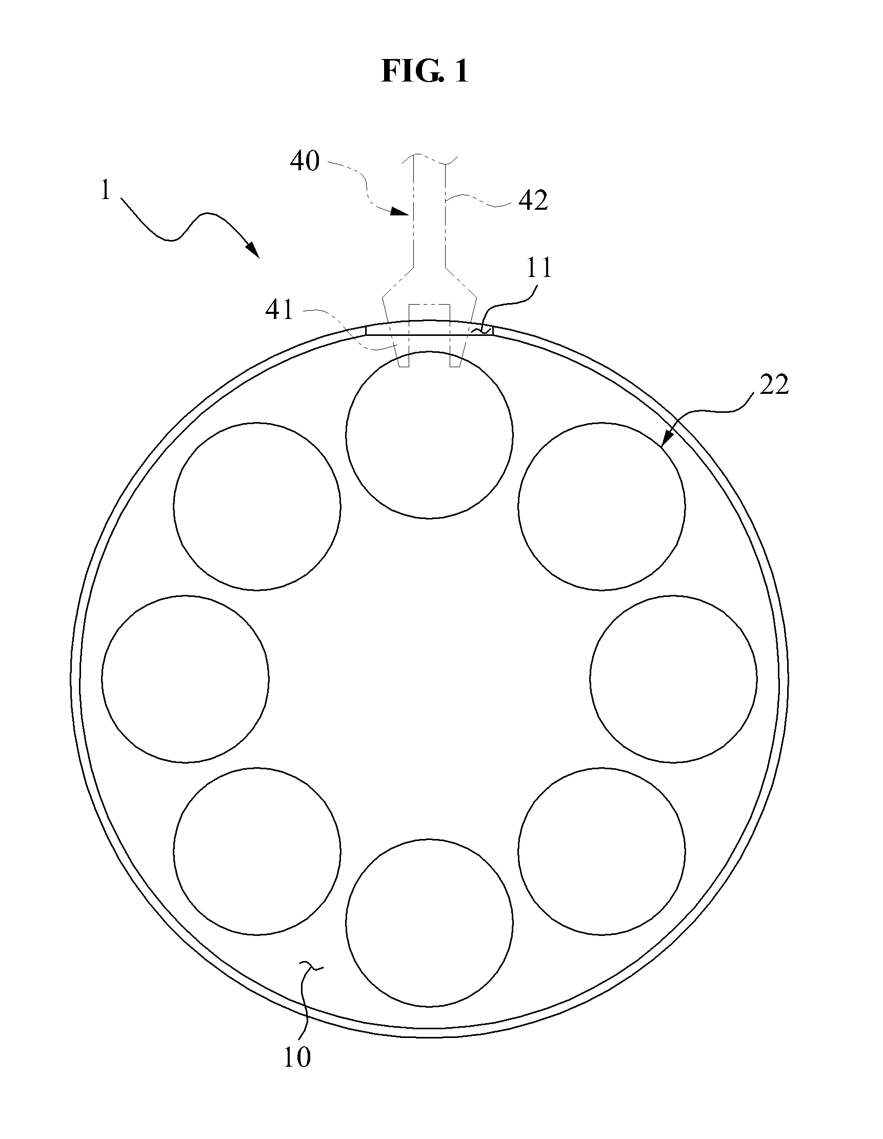
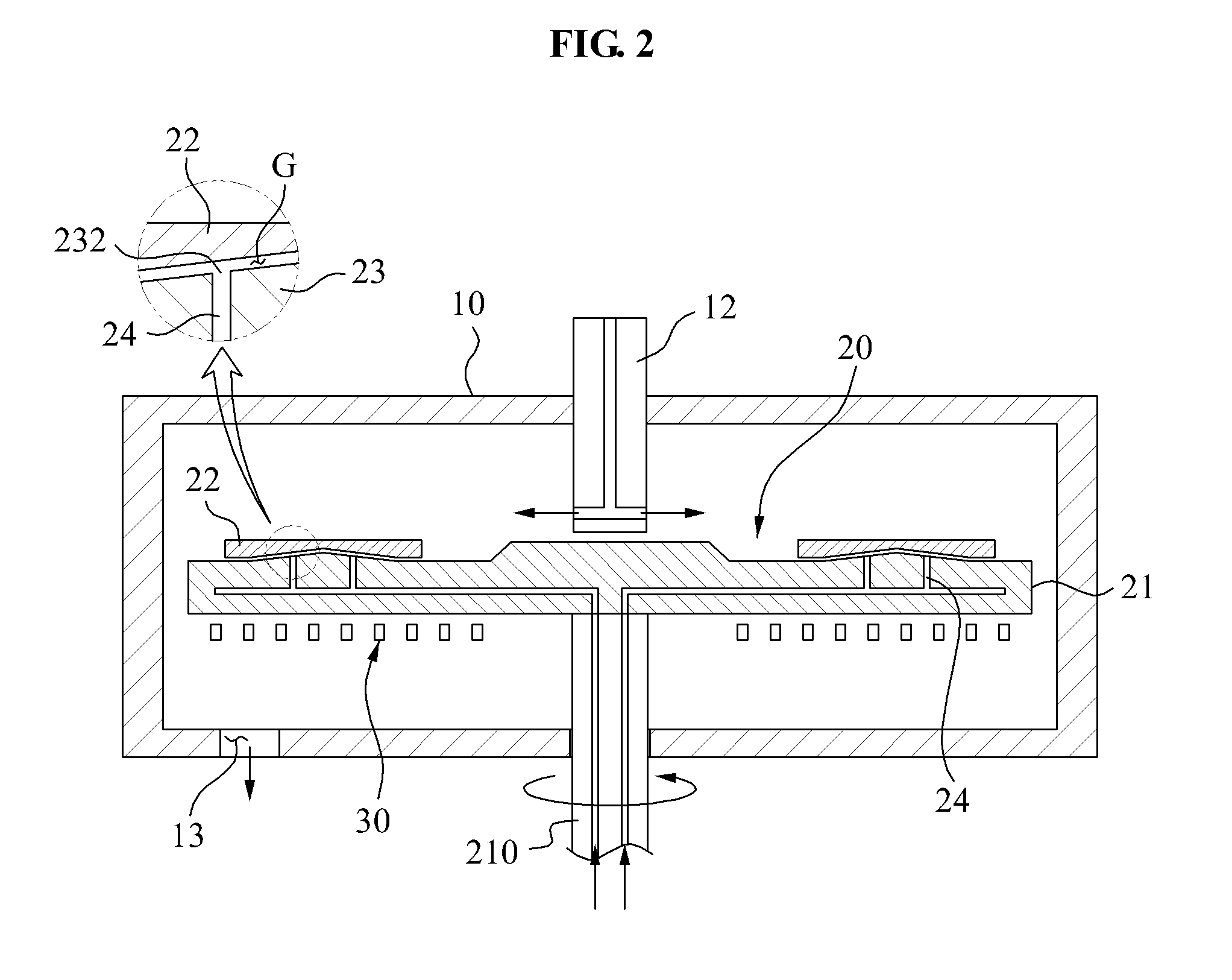
[0024]FIG. 1 illustrates a plan view of a susceptor 20 for a chemical vapor deposition (CVD) apparatus 1, according to example embodiments. FIG. 2 illustrates a sectional view of the susceptor 20 for the CVD apparatus 1. FIG. 3 illustrates a sectional view of the susceptor 20 shown in FIG. 2, where a substrate supporting unit 22 is separated. FIG. 4 illustrates a bottom perspective view of the substrate supporting unit 22.

[0025]Referring to FIGS. 1 through 4, the CVD apparatus 1 may include a reaction chamber 10 to supply a space where a chemical reaction is performed, the susceptor 20 to mount at least one substrate (not shown), a heat source 30 to heat the susceptor 20, and a transf...


PUM

PropertyMeasurementUnit
Flow rateaaaaaaaaaa
Viscosityaaaaaaaaaa
Shapeaaaaaaaaaa

Abstract

A susceptor and an apparatus for chemical vapor deposition (CVD) are provided. The susceptor includes a main body configured to include a mounting unit having an uneven plane, and a substrate supporting unit configured to be seated on the mounting unit. A bottom surface of the substrate supporting unit has a shape corresponding to a shape of the mounting unit, and the mounting unit includes a gas discharge hole to discharge gas to the substrate supporting unit. Accordingly, accurate positioning of the substrate supporting unit may not be required when the substrate supporting unit is being returned. Also, the vapor deposition may be stably performed.

Description

CROSS-REFERENCE TO RELATED APPLICATION[0001]This application claims the benefit of Korean Patent Application No. 10-2010-0076367, filed on Aug. 9, 2010, in the Korean Intellectual Property Office, the of which is incorporated herein by reference.BACKGROUND[0002]1. Field[0003]Example embodiments of the following description relate to a susceptor and a chemical vapor deposition (CVD) apparatus with the susceptor.[0004]2. Description of the Related Art[0005]A light emitting diode (LED) is a semiconductor device that converts an electrical current into light. Manufacturing processes for the LED includes an epiwafer manufacturing process, a chip manufacturing process, a packaging process, and a modularizing process.[0006]The epiwafer manufacturing process manufactures an epiwafer by growing a GaN-based crystal on a substrate using a metal organic chemical vapor deposition (MOCVD) apparatus.[0007]Generally, the substrate is supported by a satellite disc mounted to a susceptor of the MOCVD...

Claims


Application Information

Patent Timeline
IPC IPC(8): C23C16/458C23C16/455
CPCC23C16/4584C23C16/4586C23C16/4585
Inventor LEE, WON SHIN
Owner SAMSUNG ELECTRONICS CO LTD
Learn More