

Solar cell and solar cell module
a solar cell and module technology, applied in the field of solar cell and solar cell module, can solve the problems of solar cell characteristic deterioration, cracking of photoelectric conversion body, warping of solar cell, etc., and achieve the effect of preventing characteristic deterioration and increasing the manufacturing cost of the cell
- Summary
- Abstract
- Description
- Claims
- Application Information
AI Technical Summary
Benefits of technology
Problems solved by technology
Method used
Image

Examples
first embodiment
(Overall Configuration of Solar Cell Module)
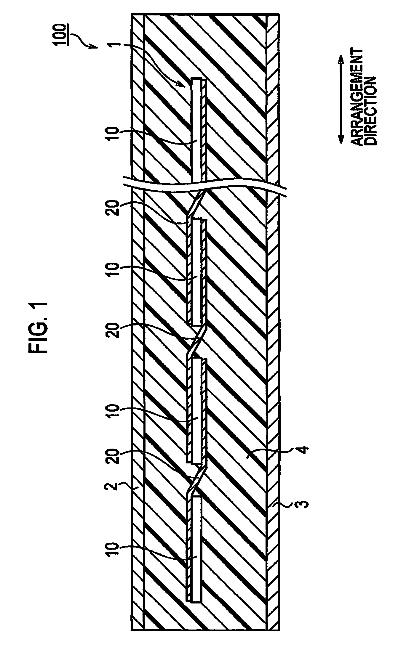
[0053]An overall configuration of a solar cell module 100 according to an embodiment of the present invention is described by referring to FIG. 1. FIG. 1 is a side view of a solar cell module 100 according to the embodiment.
[0054]The solar cell module 100 includes a solar cell string 1, a light-receiving surface side protection member 2, a back surface side protection member 3, and a sealing member 4. The solar cell module 100 is formed in such a manner that the solar cell string 1 is sealed between the light-receiving surface side protection member 2 and the back surface side protection member 3.
[0055]The solar cell string 1 includes a plurality of solar cells 10 and a plurality of wiring members 20. The solar cell string 1 is formed in such a manner that the plurality of solar cells 10 arranged in an arrangement direction are connected to each other through the plurality of wiring members 20. In other words, each of the solar cells 10 is...
second modification
of First Embodiment
[0137]Hereinafter, a second modification of the first embodiment is described by referring to the drawings. In the following description, points different from the first embodiment are mainly described. Specifically, in the modification, the description is given of a case where a plurality of connecting wires formed in one direction are arranged in the arrangement direction.
(Configuration of Solar Cell)
[0138]The configuration of the solar cell 10 according to the modification is described by referring to FIG. 9. FIG. 9(a) is a plan view of the solar cell 10 viewed from the light-receiving surface side. FIG. 9(b) is a plan view of the solar cell 10 viewed from the back surface side. Note that, the connecting wire group 37A and the connecting wire group 37B in the modification have the same configurations. Thus, only the connecting wire group 37A is mainly described below.
[0139]The connecting wire group 37A is formed on the light-receiving surface FS of the photoele...
second embodiment
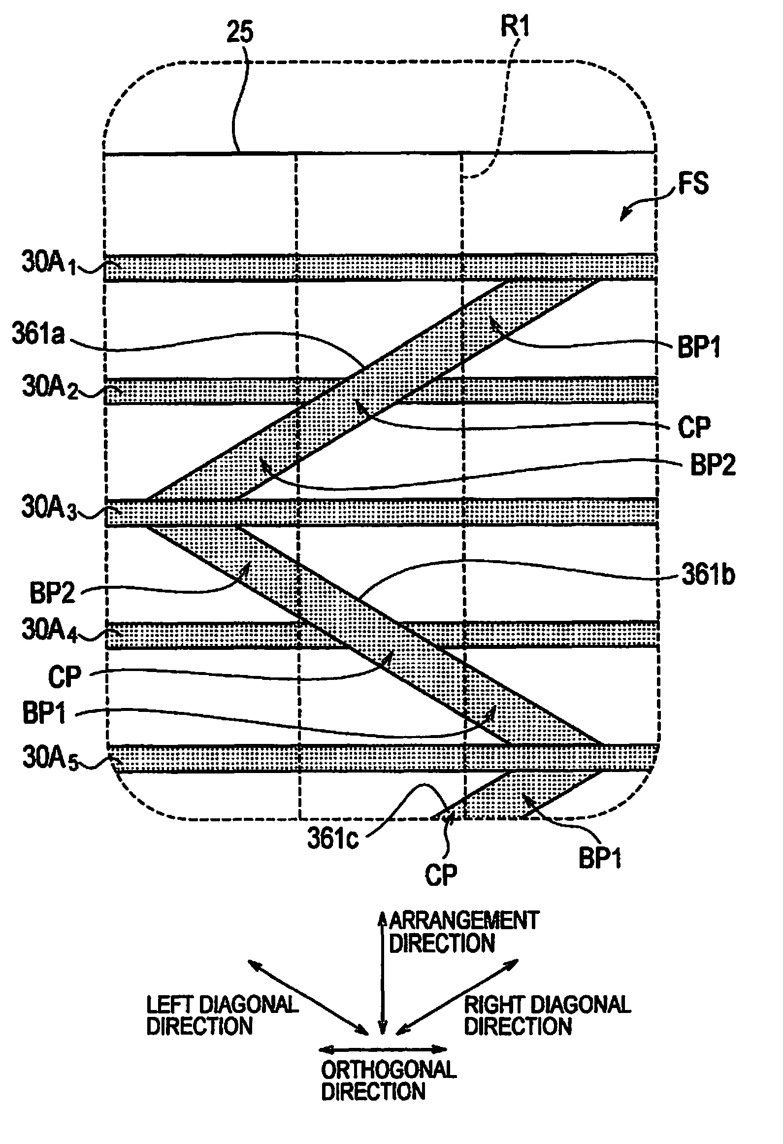
[0149]Hereinafter, a second embodiment of the present invention is described by referring to the drawings. In the following description, points different from the first embodiment are mainly described. Specifically, in the second embodiment, the description is give of a case where two connecting wires 351 are connected to two light-receiving surface side fine-line electrodes 30A.
(Configuration of Solar Cell)
[0150]The configuration of the solar cell 10 according to the second embodiment is described by referring to FIG. 11. FIG. 11(a) is a plan view of the solar cell 10 viewed from the light-receiving surface side. FIG. 11(b) is a plan view of the solar cell 10 viewed from the back surface side. Note that, the connecting wire group 38A and the connecting wire group 38B according to the second embodiment have the same configurations. Thus, only the connecting wire group 38A is mainly described below.
[0151]As shown in FIG. 11(a), in a plan view of the light-receiving surface FS, the co...
PUM
 Abstract
Description
Claims
Application Information