
Network analyzer with an n-port network having at least two ports for measuring the wave parameters of a measurement object

a network analyzer and wave parameter technology, applied in frequency analysis, resistance/reactance/impedence, instruments, etc., can solve the problem that the type of measurement of dynamic measurement objects is not possible with conventional network analyzers

Inactive Publication Date: 2012-02-09
SIEMENS AG
View PDF4 Cites 3 Cited by
  • Summary
  • Abstract
  • Description
  • Claims
  • Application Information

AI Technical Summary

Benefits of technology

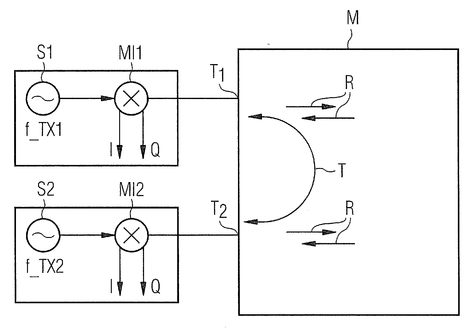
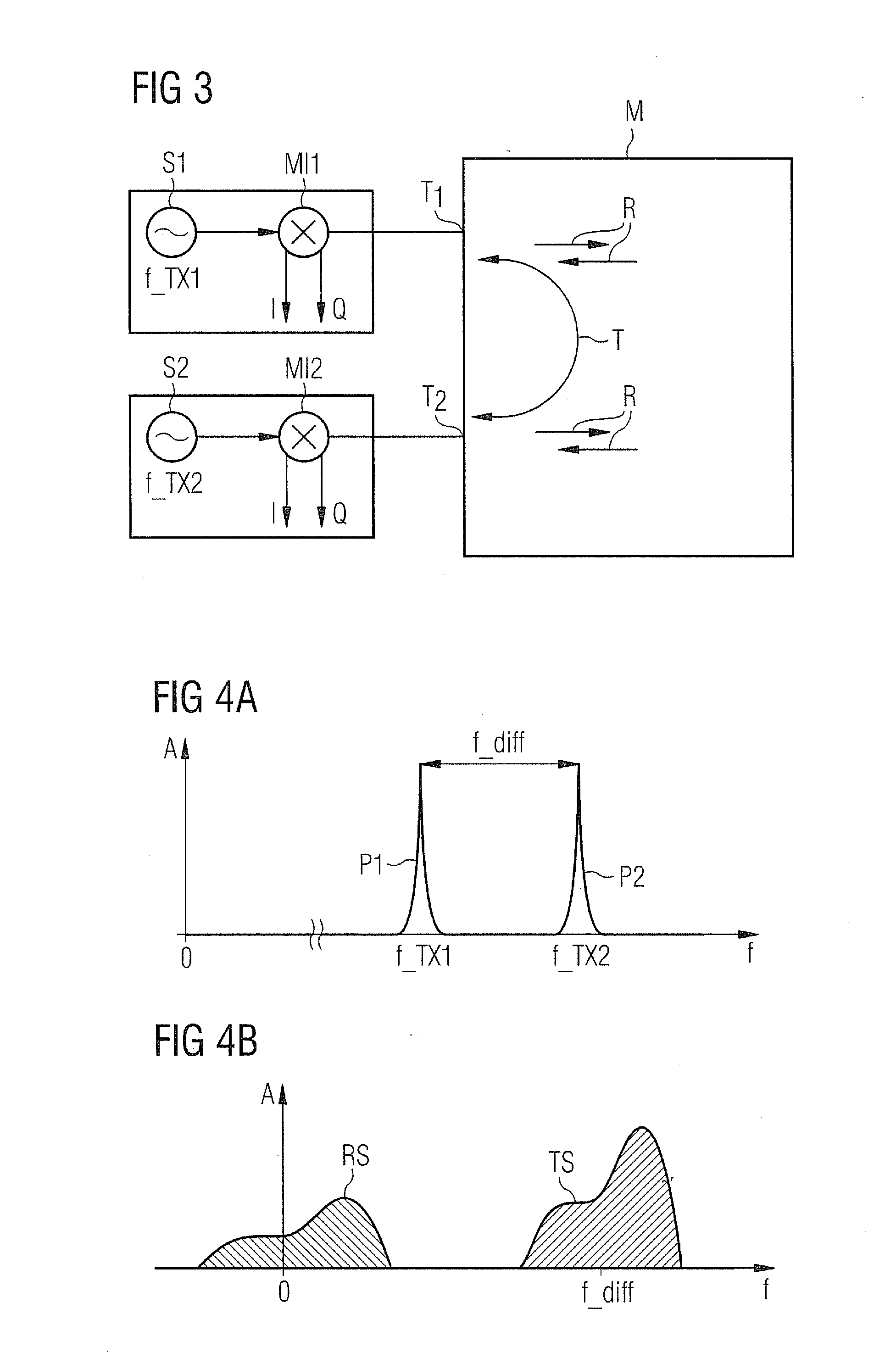
[0007]The inventive network analyzer is characterized in that the said at least two ports of the n-port device are supplied, during operation of the network analyzer, with different radio-frequency signals, the frequencies or frequency bands of which are offset with respect to one another by a frequency offset, the reflected and transmitted signal components of the radio-frequency signals being measured at the same time at the said at least two ports. The invention is based on the finding that a suitable separation of the spectra of the reflected and transmitted signal components can be achieved by means of a corresponding frequency offset, so that all scattering parameters of a plurality of ports can be measured at the same time. In this way, measurement objects that are rapidly changing dynamically can be captured. In this respect, the changing scattering parameters of the measurement object over time can be measured continuously. This type of measurement of dynamic measurement objects is not possible with conventional network analyzers due to the sequential measurement of the scattering parameters.
[0008]In a preferred embodiment of the inventive network analyzer, the frequency offset between the radio-frequency signals is sufficiently large in this respect so that, with regard to each port, the frequency spectra measured for the reflected and transmitted signal components do not overlap. This can be achieved by ensuring that the difference between the frequencies is at least as large as the sum of the maximum frequency deviation of the reflection spectrum from the corresponding carrier frequency and the maximum frequency deviation of the transmission spectrum from the corresponding, albeit offset by the frequency offset, carrier frequency. In this way, a clear separation is ensured between the two frequency spectra. Nevertheless, an overlapping of the frequency spectra can also be permitted where relevant, in particular if only specific components of the frequency spectra are of interest in the measurement being carried out.
[0009]In order to prevent, as far as possible, any distortion of the measurement in the event of a frequency dependence of the scattering parameters, the frequency offset between the radio-frequency signals is not selected too large in a preferred embodiment. In one variant, the frequency offset is therefore smaller than the smallest and / or largest frequency or center frequency of the frequency band of the different radio-frequency signals. For example, the frequency offset can be less than or equal to 50%, and preferably less than or equal to 25%, and particularly preferably less than or equal to 10% of the smallest and / or largest frequency or center frequency of the frequency band of the different radio-frequency signals.
[0012]In a further, preferred embodiment of the inventive network analyzer, each port of the n-port device includes a waveguide supplied via a separate radar, the operating frequencies of the radars differing from each other by the frequency offset. With regard to specific applications, for example for measuring the scattering parameters of rotating vanes of a gas turbine, the operation of one of the radars at a frequency of 80 GHz and another of the radars at 80.01 GHz, i.e. with a frequency offset of 10 MHz, has proved useful.

Problems solved by technology

This type of measurement of dynamic measurement objects is not possible with conventional network analyzers due to the sequential measurement of the scattering parameters.

Method used


Image

  • Network analyzer with an n-port network having at least two ports for measuring the wave parameters of a measurement object
  • Network analyzer with an n-port network having at least two ports for measuring the wave parameters of a measurement object
  • Network analyzer with an n-port network having at least two ports for measuring the wave parameters of a measurement object

Examples


Embodiment Construction

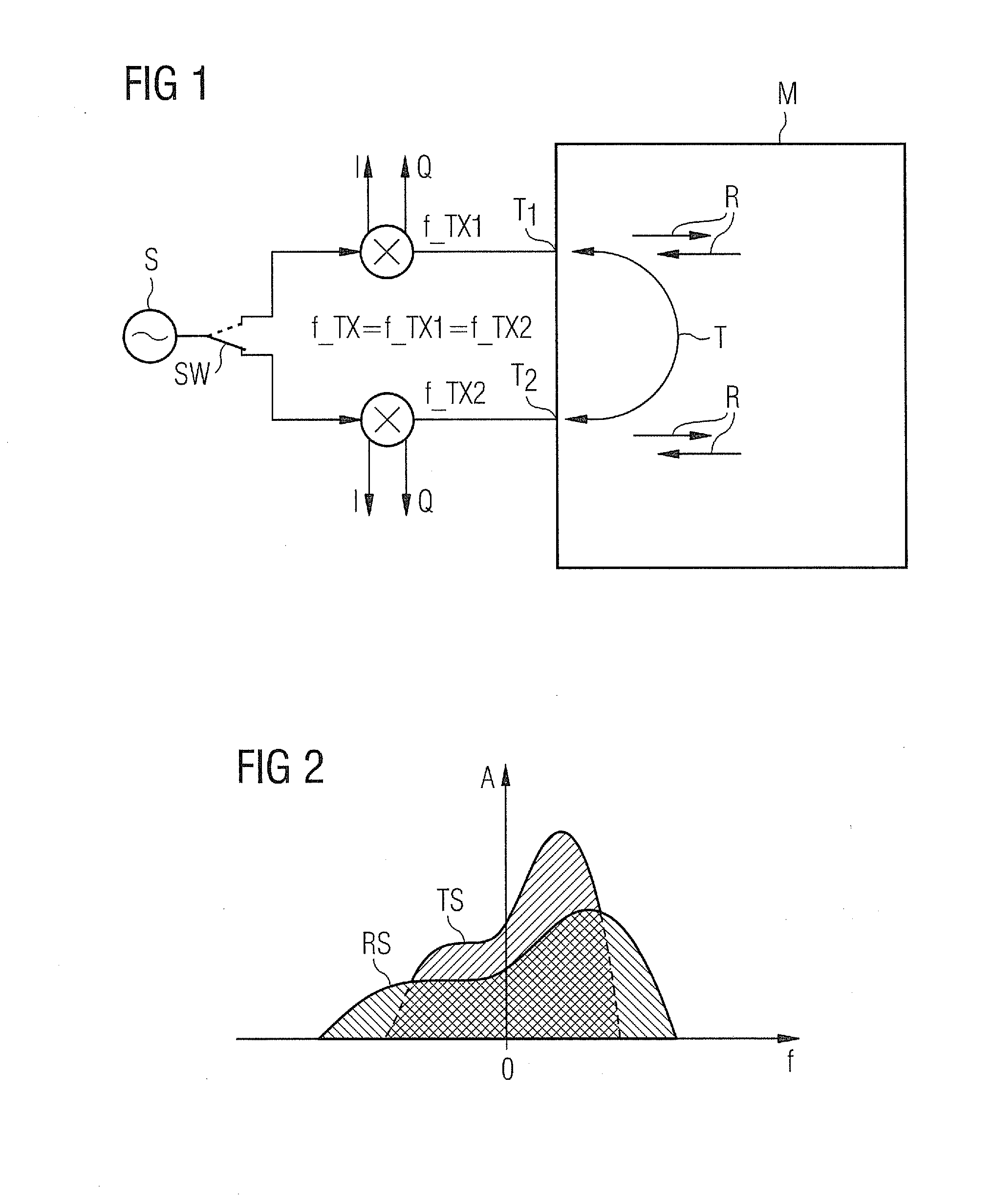
[0021]FIG. 1 shows a schematic representation of a network analyzer with a conventional n-port circuit. The analyzer includes a radio-frequency signal source S, which emits a radio-frequency signal with the frequency f_TX. This signal is fed via a switch SW to one of two signal branches in each case, each signal branch representing a port T1 or T2, which is formed by means of the passage of the respective signal branch to a measurement object M. In this respect, the measurement object M can be regarded as an object with unknown properties in the nature of a black box and is therefore indicated in the form of a rectangle. Now the aim of the measurement carried out with the aid of the network analyzer is to ascertain the wave parameters of the measurement object M via the ports T1 or T2. These wave parameters, which are also referred to as s-parameters or scattering parameters, indicate how much of the power fed in to a port is reflected or transferred from the one port to the other p...


PUM


Abstract

A network analyzer includes an n-port network with two ports for measuring wave parameters of a measurement object. Each port has a feed for a radio-frequency signal from a signal source. Signal components of the radio-frequency signal fed into the respective port are reflected at the measurement object and the signal components of one or more radio-frequency signals fed into at least one other port are transmitted through the measurement object to the respective port are measured as wave parameters. The two ports are supplied with different radio-frequency signals, wherein frequencies or frequency bands are offset with respect to one another by a frequency offset. Reflected and transmitted signal components of the radio-frequency signals are measured at the same time at the two ports.

Description

CROSS REFERENCE TO RELATED APPLICATIONS[0001]This application is the US National Stage of International Application No. PCT / EP2010 / 052372 filed Feb. 25, 2010, and claims the benefit thereof. The International Application claims the benefits of German Patent Application No. 10 2009 016 028.0 DE filed Apr. 2, 2009. All of the applications are incorporated by reference herein in their entirety.FIELD OF INVENTION[0002]The invention relates to a network analyzer with an n-port device having at least two ports for measuring the wave parameters of a measurement object and also a corresponding method for measuring parameters of a measurement object with the aid of a network analyzer of this type.BACKGROUND OF INVENTION[0003]Network analyzers with n-port devices are used for measuring and therefore characterizing measurement objects by way of their wave parameters. These wave parameters, which are also referred to as s-parameters or scattering parameters, specify in this respect, with regard...

Claims


Application Information

Patent Timeline
Patent Type & Authority Applications(United States)
IPC IPC(8): G01S13/02G01R23/14
CPCG01R27/28
Inventor POPRAWA, FLORIANSCHICHT, ANDREASSEISENBERGER, CLAUSZIROFF, ANDREAS
Owner SIEMENS AG
Learn More