Microphone unit and highly directional microphone

a microphone and microphone technology, applied in the field of microphones, can solve the problems of diaphragms increasing vibration noise in the low frequency range, wind noise, and large wind noise in particular, and achieves the effects of reducing acoustic impedance, high directivity, and sufficient noise reduction

Inactive Publication Date: 2012-02-09
AUDIO-TECHNICA
View PDF0 Cites 9 Cited by
  • Summary
  • Abstract
  • Description
  • Claims
  • Application Information

AI Technical Summary

Benefits of technology

[0014]In the microphone unit and the highly directional microphone according to the present invention, the unit casing has the shoulder positioning the built-in components and the groove in the radial direction provided in the shoulder and in communication with the groove in the axial direction. The groove in the axial direction and the groove in the radial direction configure the connecting path between the front acoustic terminal and the rear acoustic terminal. Thus, enlarging the connecting path to reduce the acoustic impedance has no adverse impact on acoustic properties. Even a highly directional microphone having a high directivity in low frequencies can achieve a sufficient noise reduction effect.

Problems solved by technology

Such a difference causes wind noise.
With the diaphragm of the microphone unit provided between the front acoustic terminal and the rear acoustic terminal, the pressures difference is generated between the front and rear of the diaphragm, thus resulting in large wind noise in a low frequency range in particular.
Application of the acoustic mass to the diaphragm increases vibration noise in the low frequency range.
Since a displacement of the diaphragm due to wind or vibration, however, modulates audio signals, use of the low-cut filter results in an insufficient noise reduction effect.
This configuration causes an inevitable increase in the size of the acoustic tube and thus an increase in the size of the entire device.
If provided with an acoustic tube having an entire length of 100 mm or more, for example, in order to ensure high directivity in a low frequency range, however, the highly directional microphone shown in FIG. 6 does not have a sufficient noise reduction effect unless the acoustic impedance of the connecting path C′ having a width B′ is lowered in the unit casing 4.
The axis A of the microphone unit 1 may then be moved to a position A′, for example, thus adversely affecting the acoustic performance of the microphone unit 40.
The metal mesh 50 thus serves as acoustic resistance, causing an adverse effect on the acoustic performance in some cases.

Method used


Image

  • Microphone unit and highly directional microphone
  • Microphone unit and highly directional microphone
  • Microphone unit and highly directional microphone

Examples


Embodiment Construction

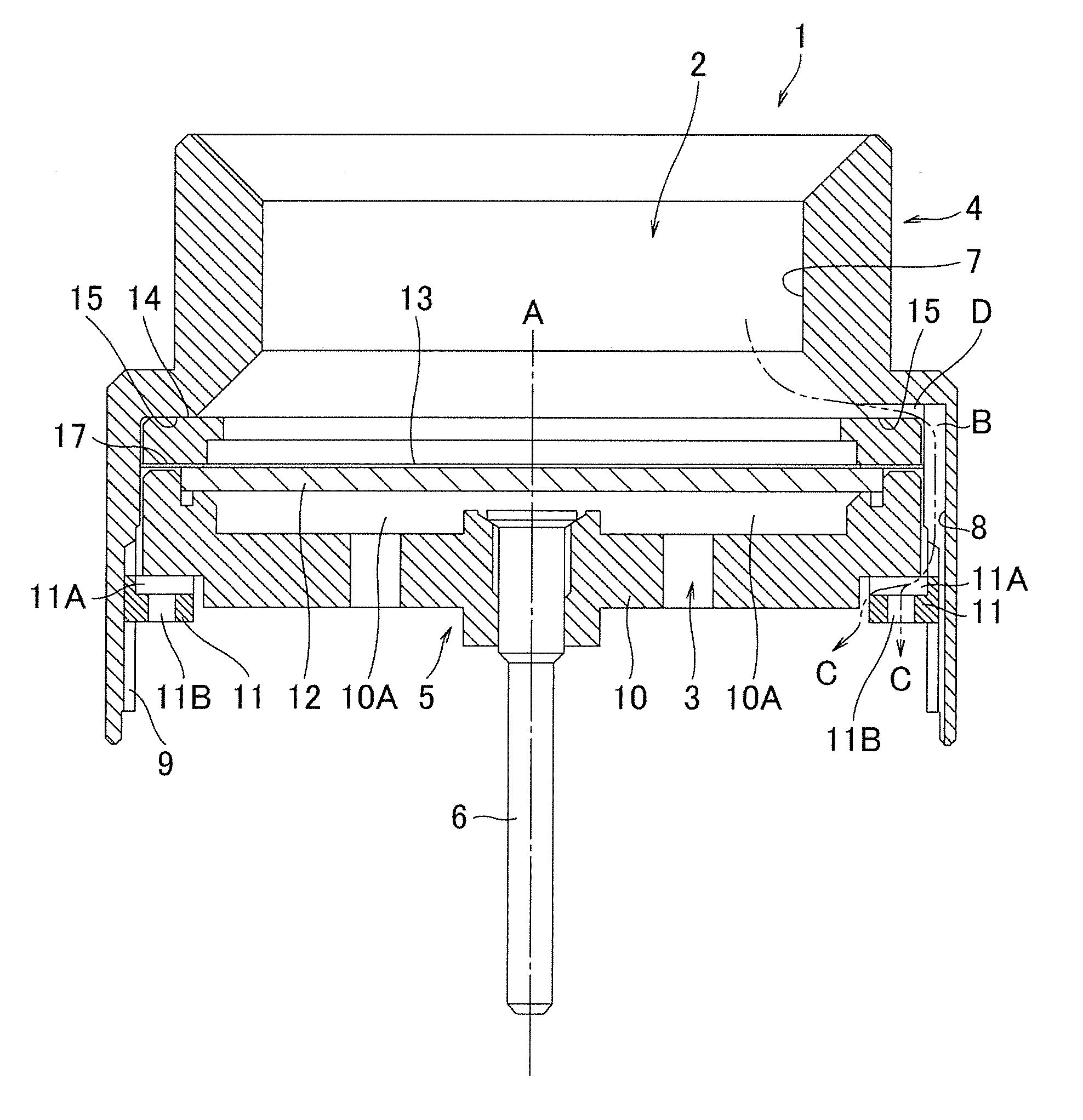
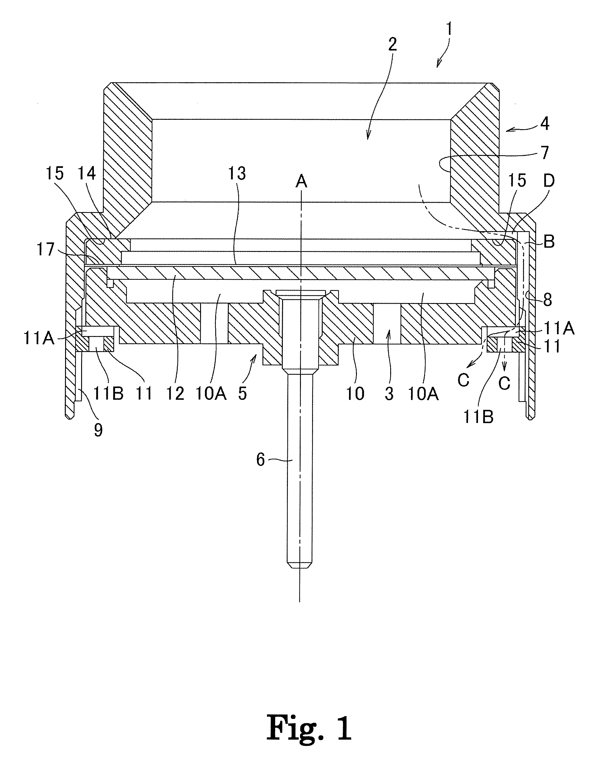
[0022]The embodiments of a microphone unit and a highly directional microphone according to the present invention are explained below with reference to the attached drawings. The configurations of the microphone unit and the highly directional microphone according to the present invention are not limited to the embodiments. The entirety or a portion of the components built in a unit casing may be referred to as “built-in components.” Components similar to those in a conventional example shown in FIG. 6 are assigned with identical reference numerals.

[0023]In FIG. 1, a microphone unit 1 has a diaphragm 13 composed of a disk thin film and vibrating in response to sound waves; a ring diaphragm holder 14 to which the periphery of the diaphragm 13 is fixed; a ring spacer 17; a disk fixed electrode 12 forming a capacitor and disposed oppositely to the diaphragm 13 with a space therebetween provided by the spacer 17; an electrode 6; an insulating washer 10 composed of an insulating material...


PUM


Abstract

A microphone unit has a diaphragm vibrating in response to sound waves; a unit casing accommodating the diaphragm; and a connecting path connecting a front acoustic terminal and a rear acoustic terminal. The unit casing has a small-diameter internal periphery defining the front acoustic terminal; a large-diameter internal periphery accommodating built-in components including the diaphragm; and a shoulder provided between the small-diameter internal periphery and the large-diameter internal periphery and positioning the built-in components. The unit casing has a groove in an axial direction provided in the large-diameter internal periphery and a groove in a radial direction provided in the shoulder and being in communication with the groove in the axial direction. The groove in the axial direction and the groove in the radial direction configure the connecting path.

Description

BACKGROUND OF THE INVENTION[0001]1. Field of the Invention[0002]The present invention relates to a microphone unit suitable for a highly directional microphone, the microphone unit allowing—vibration noise and wind noise to be reduced and exhibiting enhanced acoustic performance. The present invention also relates to a highly directional microphone including the microphone unit.[0003]2. Related Background Art[0004]A highly directional microphone includes a microphone unit incorporated into a long and thin acoustic tube. Wind blowing at the open end of the acoustic tube causes a pressure difference between the front and rear of a diaphragm included in the microphone unit. Such a difference causes wind noise. The highly directional microphone has a long distance between a front acoustic terminal, which is provided in the front end of the acoustic tube as a sound wave inlet, and a rear acoustic terminal, which is provided in the rear end of the acoustic tube. Accordingly, a pressure di...

Claims


Application Information

Patent Timeline
Patent Type & Authority Applications(United States)
IPC IPC(8): H04R1/00
CPCH04R1/02H04R31/00H04R1/06H04R19/04
Inventor AKINO, HIROSHI
Owner AUDIO-TECHNICA
Why Eureka
Try Eureka