Ramp

a technology of ramps and ramps, applied in the field of ramps, can solve the problems of ramps that must be installed often, the design of many ramps is unforgiving, and the installation of ramps is often beyond the normal user's control,

Inactive Publication Date: 2012-02-16
DLP
View PDF8 Cites 14 Cited by
  • Summary
  • Abstract
  • Description
  • Claims
  • Application Information

AI Technical Summary

Benefits of technology

[0019]According to a third aspect of the invention, there is provided a ramp comprising a user support element, an edge element at an edge of the user support element, and a height adjustable ramp support which includes a foot and two arms, each arm having a part-spherical pivot element at a proximal end thereof, each pivot element being abuttable with the other pivot element to provide a part-spherical head element, the foot including a cup having a part-spherical bearing surface which is complimentarily shaped to captively engage the part-spherical head element whereby the pivot elements can independently pivot relative to each other and the foot can pivot independently of the pivot elements in at least the plane of the arms and laterally of the arms.

Problems solved by technology

However, even though modular in nature to accommodate different installation environments, the ramps are still onerous to install, typically requiring significant amounts of cutting, fastening, adjustment, and even welding.
This kind of installation is generally beyond the normal user and requires specialist trained installers.
Furthermore, the design of many ramps is unforgiving if a user knocks or bumps for example into its handrail.
Additionally, ramps must often be installed on uneven ground, requiring particular positioning and adjustment of the ground supports.

Method used


Image

  • Ramp
  • Ramp
  • Ramp

Examples


Embodiment Construction

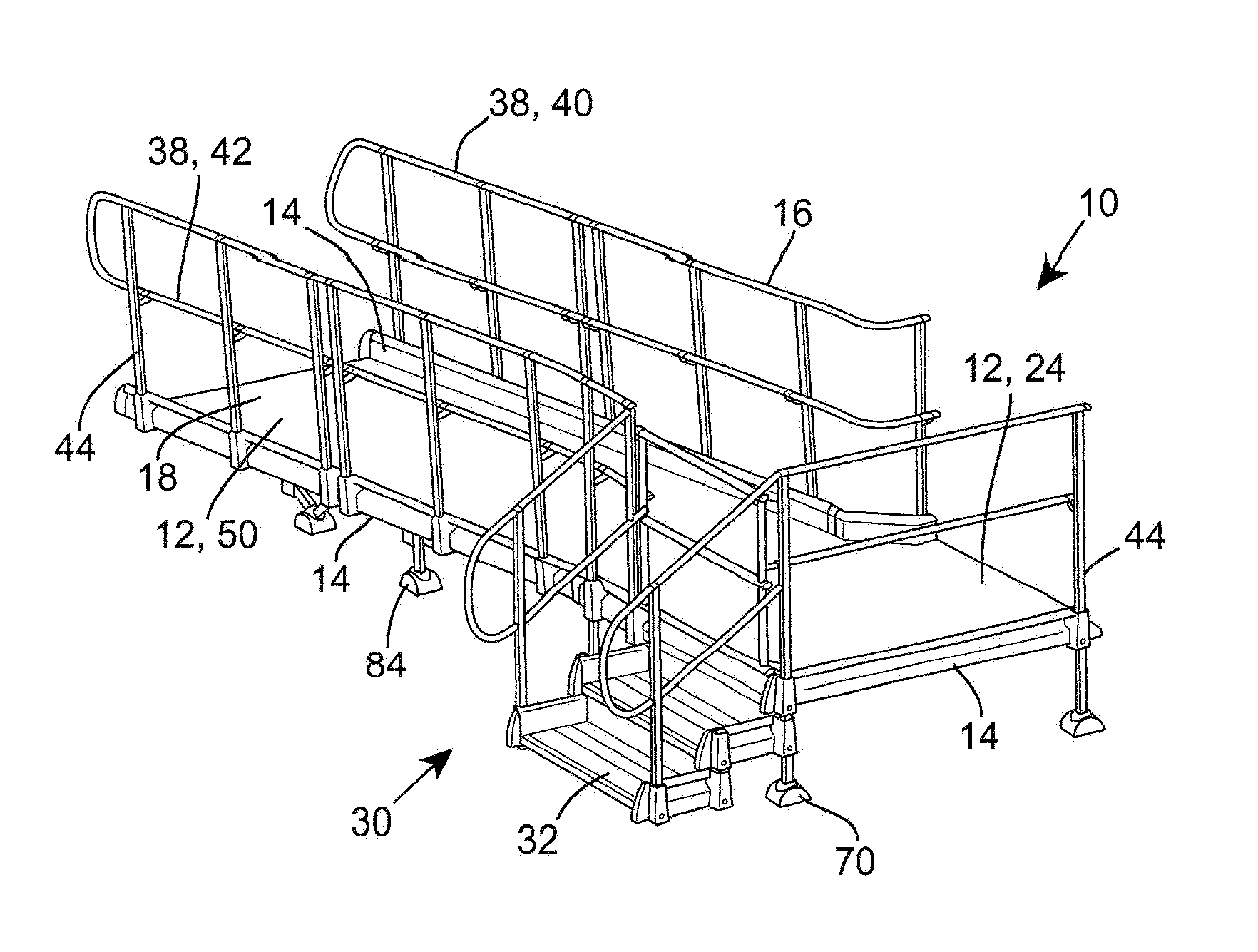
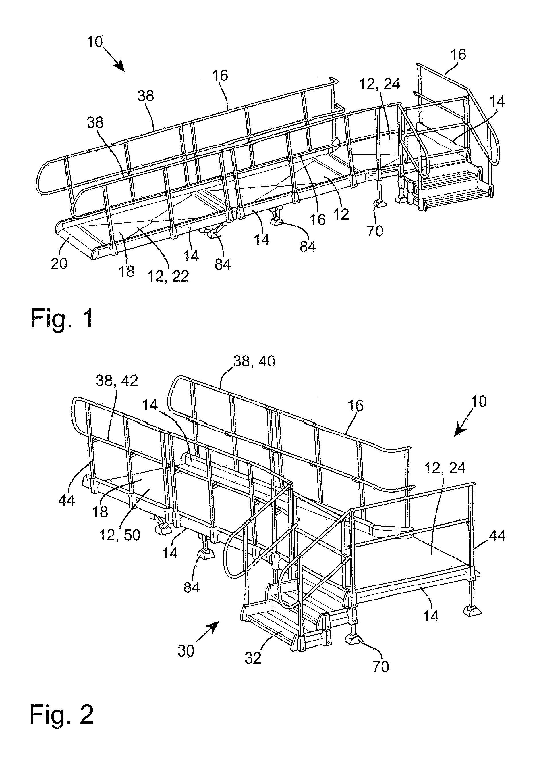
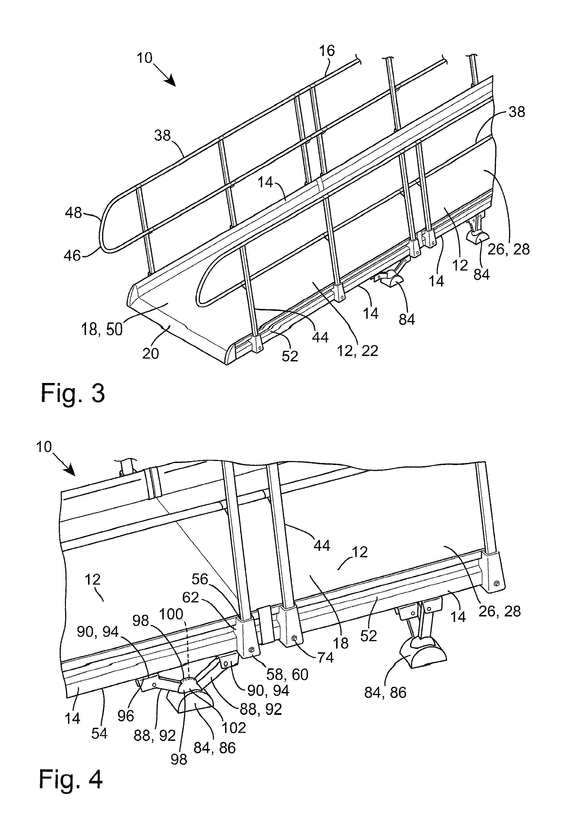
[0031]Referring to the drawings, there is shown a ramp 10 which is modular in nature, comprising a plurality of user support elements 12, a plurality of edge elements 14, and a handrail 16. The user support elements 12 are common for a ramped portion 18 of the ramp 10, thereby enabling accommodation of differing lengths. A selectively connectable tapering leading edge element 20 is also utilised on a front edge of a leading user support element 22 to aid admission of wheelchairs onto the ramped portion 18 and to facilitate disembarkation.

[0032]The user support elements 12 also include a top platform element 24 which is generally level for positioning at the height of the building entrance / exit. The user support elements 12 are all selectively interconnectable, for example, using snap-fit or drop-in tongue and groove joints. If separate screw-threaded fasteners for interconnecting the user support elements 12 can be avoided, this simplifies installation.

[0033]Upper surfaces 26 of the...


PUM


Abstract

The present invention provides two aspects :
A ramp which comprises a user support element, an edge element at an edge of the user support element, a handrail, a support connector which is slidably engagable with the edge element, an elongate upright handrail support, and an adjustable elongate depending ramp support. The handrail support and the ramp support are coaxially held by the support connector;
A ramp which comprises a user support element, an edge element at an edge of the user support element, and a height adjustable ramp support which includes a foot and two arms pivotably engaged with the foot. Each arm has a slider pivotably engaged at its distal end remote from the foot, and each slider is slidably engagable with the edge element for lengthwise adjustment of the ramp support along the edge element and for slidable adjustment relative to each other so as to set a distance between the edge element and the foot. Each slider is further fixedly holdable in place to maintain its set position; and
A ramp which comprises a user support element, an edge element at an edge of the user support element, and a height adjustable ramp support which includes a foot and two arms. Each arm has a part-spherical pivot element at a proximal end thereof, and each pivot element is abuttable with the other pivot element to provide a part-spherical head element. The foot includes a cup having a part-spherical bearing surface which is complimentarily shaped to captively engage the part-spherical head element, whereby the pivot elements can independently pivot relative to each other and the foot can pivot independently of the pivot elements in at least the plane of the arms and laterally of the arms.

Description

[0001]The present invention relates to a ramp, and more particularly to a modular ramp which is suitable for an elderly and / or infirm user, possibly being wheelchair bound.BACKGROUND OF THE INVENTION[0002]Ramps are widely used to provide access for the disabled to their domestic properties, places of work and shops. However, even though modular in nature to accommodate different installation environments, the ramps are still onerous to install, typically requiring significant amounts of cutting, fastening, adjustment, and even welding. This kind of installation is generally beyond the normal user and requires specialist trained installers.[0003]Furthermore, the design of many ramps is unforgiving if a user knocks or bumps for example into its handrail. This is of particular concern for an older user who is liable to bruise and mark much more easily.[0004]Additionally, ramps must often be installed on uneven ground, requiring particular positioning and adjustment of the ground suppor...

Claims


Application Information

Patent Timeline
Patent Type & Authority Applications(United States)
IPC IPC(8): E04F11/00
CPCE04F11/002E04F11/02E04F11/1812E04F2011/007E04F11/00E04F11/18
Inventor PETERS, ANDREW
Owner DLP
Why Eureka
Try Eureka