
Windscreen wiper device

Inactive Publication Date: 2012-02-16
FEDERAL MOGUL SA
View PDF8 Cites 17 Cited by
  • Summary
  • Abstract
  • Description
  • Claims
  • Application Information

AI Technical Summary

Benefits of technology

[0007]It is an object of the invention to obviate this disadvantage, in the sense that at minimum costs—without using complex machinery and additional tools—a simple though effective windscreen wiper device is proposed which fits on all kinds of different cars.
[0008]Thereto, according to the invention a windshield wiper arm mentioned in the preamble is characterized in that the windscreen wiper device further comprises a connecting device for detachably connecting the wiper blade directly to the mounting head, wherein the connecting device is positioned near one end of the wiper blade, and wherein the connecting device, at the location of its attachment to the mounting head, is located in its entirety inside the mounting head. Preferably, the windscreen wiper device further comprises a connecting piece positioned near the other end of the wiper blade and connected to one end of the longitudinal strip. The wiper arm according to the present invention refrains from the use of an intermediate oscillating arm, thereby avoiding an articulation between the oscillating arm and the wiper blade, as well as between the mounting head and the oscillating arm. This not only ensures that less parts have to be used in manufacturing the windscreen wiper device with all advantages involved (such as cheaper, lighter, less plastic material sensitive to UV-light), but also that disadvantages like wear are obviated.
[0009]Further, by directly connecting the connecting device to the mounting head, the wiper blade is mounted closer to the windscreen to be wiped, so that the wiping properties are improved. Also, by locating the connecting device in its entirety inside the mounting head, a very strong connection between is formed that can withstand large torque. Advantageously, the connecting device and the connecting piece are connected to the wiper blade at opposite ends thereof.
[0019]In a further preferred embodiment of a windscreen wiper device in accordance with the invention the longitudinal strip is biassed in such a way that its curvature radius near the connecting device is smaller than that its curvature radius near the other end of the wiper blade, all seen in dismounted position. in other words, in dismounted position the wiper blade has an asymmetric shape, seen along its middle transverse plane perpendicular to a windscreen to be wiped. Thus, the wiper blade is able to follow any curvature of a windscreen to be wiped, while the wiper blade is pressed onto the windscreen to be wiper with sufficient force to enhance the wiping properties.
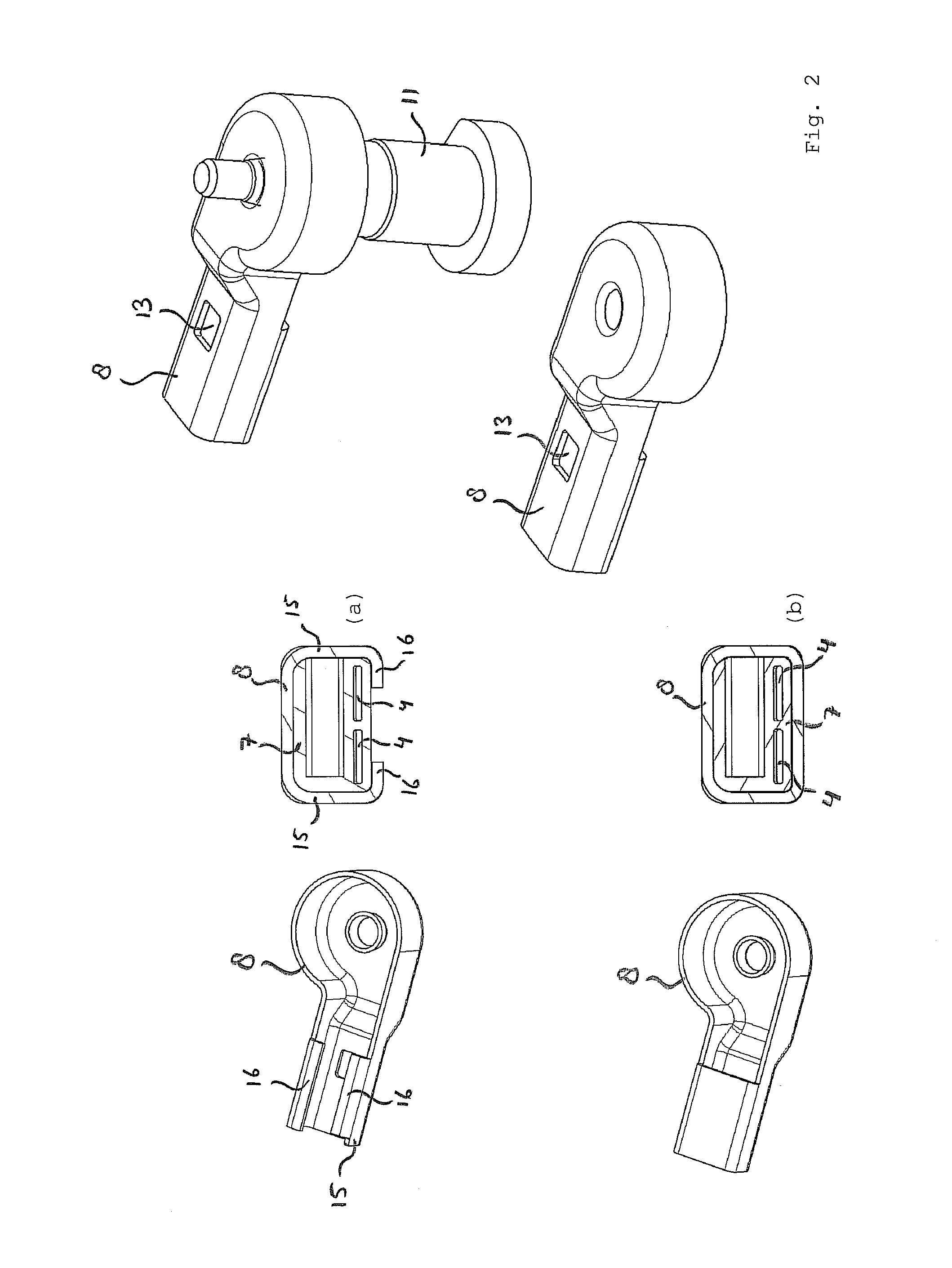
[0023]In a further preferred embodiment of a windscreen wiper device according to the invention the hole is provided in a base of the U-shaped or O-shaped cross-section of the mounting head. In this embodiment the resilient tongue may be provided on an upper part of the connecting device. In addition thereto or instead thereof the connecting device may be provided with at least two lateral resilient tongues extending outwardly, wherein each tongue engages in a correspondingly shaped hole provided in each leg of the U-shaped or O-shaped cross-section of the mounting head. the holes preferably have a closed circumference. Such closed holes enhance the retention of the connection device onto the mounting head in all possible directions, particularly both horizontally and vertically.

Problems solved by technology

A disadvantage of the windscreen wiper arm known from the above European patent publication is that it comprises many complex parts with a dedicated shape, wherein reference is made to the oscillating arm described therein consisting of a plastic arm member at one end thereof pivotally connected to a mounting head by means of a pivot pin and at the other end thereof folded around a rod-like part.
Obviously, this needs complex machinery, tools, with all the expenses involved.

Method used


Image

  • Windscreen wiper device
  • Windscreen wiper device
  • Windscreen wiper device

Examples


Embodiment Construction

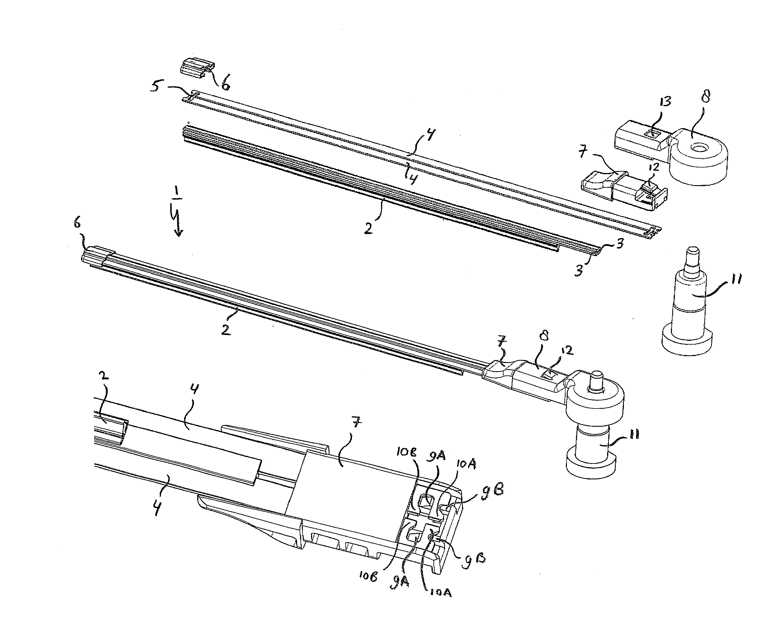
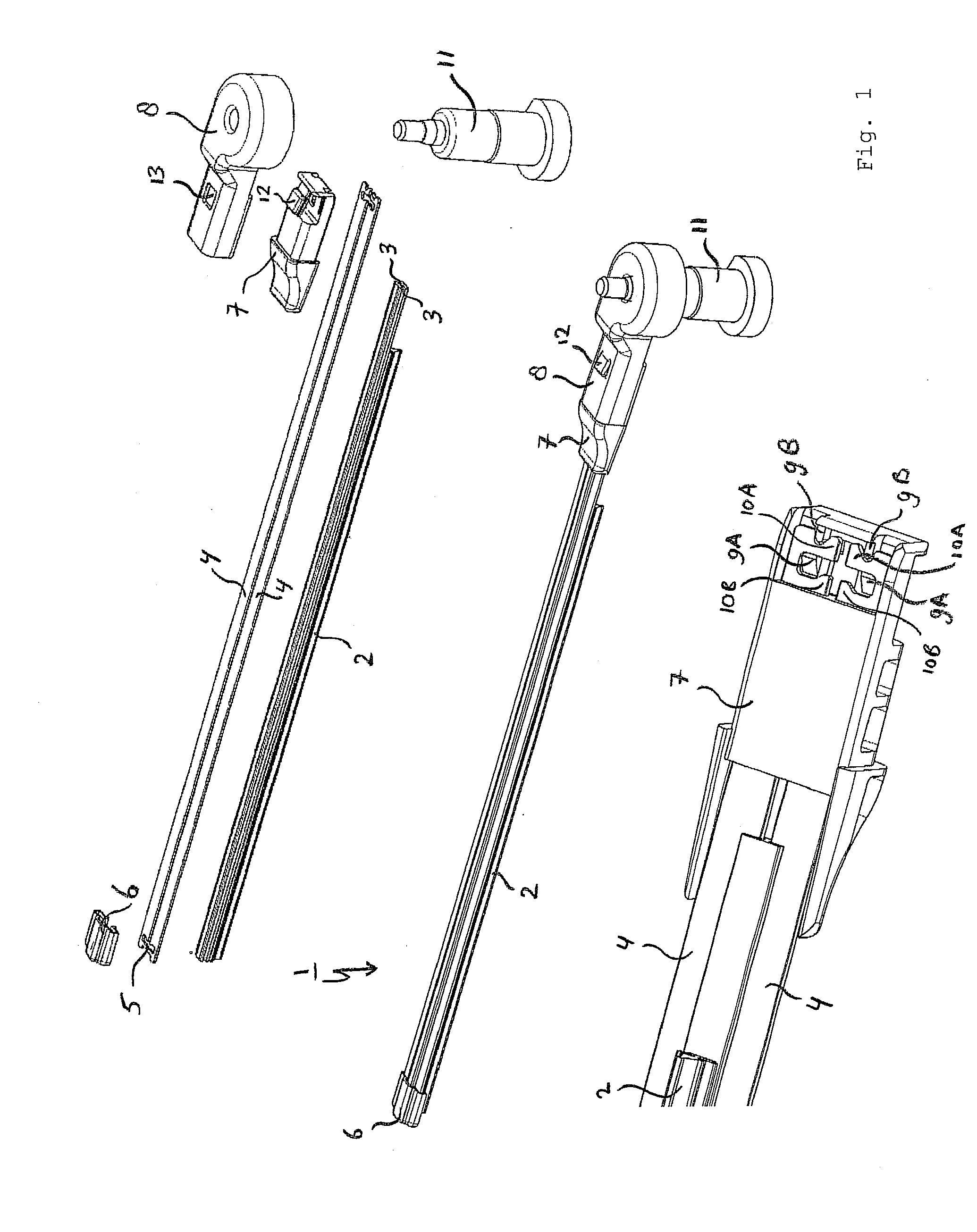
[0030]The windscreen wiper device 1 is built up of an elastomeric wiper blade 2, in the longitudinal sides of which opposing longitudinal grooves 3 are formed, and of longitudinal strips 4 made of spring band steel, which are fitted in the longitudinal grooves 3. The strips 4 form a flexible carrier element for the wiper blade 2, as it were, which is thus biassed in a curved position (the curvature in operative position being that of a windscreen to be wiped). Neighbouring ends 5 of the strips 4 at one end of the wiper blade 2 are interconnected by means of a connecting piece 6 or “end cap” functioning as clamping member. In this embodiment, the connecting piece 6 is a separate constructional element, which may be form-locked (“positive locking” or “having a positive fit”) or force-locked to the ends 5 of the strips 4. In another preferred embodiment, the connecting piece 6 is in one piece with the strips 4 made of spring band steel. In the latter case the connecting piece 6 forms a...


PUM


Abstract

A windscreen wiper device, particularly for automobiles, comprising an elastic, elongated carrier element, as well as an elongated wiper blade of a flexible material, which can be placed in abutment with a windscreen to be wiped, which wiper blade is of the flat blade type and includes at least one groove, in which groove a longitudinal strip of the carrier element is disposed, wherein the windscreen wiper device further comprises a mounting head for transferring a reciprocal movement to the wiper blade, with the special feature that the windscreen wiper device further comprises a connecting device for detachably connecting the wiper blade directly to the mounting head, wherein the connecting device is positioned near one end of the wiper blade, and wherein the connecting device, at the location of its attachment to the mounting head, is located in its entirety inside the mounting head.

Description

BACKGROUND OF THE INVENTION [0001]1. Technical Field[0002]The invention relates to a windscreen wiper device, particularly for automobiles, comprising an elastic, elongated carrier element, as well as an elongated wiper blade of a flexible material, which can be placed in abutment with a windscreen to be wiped, which wiper blade is of the flat blade type and includes at least one groove, in which groove a longitudinal strip of the carrier element is disposed, wherein the windscreen wiper device further comprises a mounting head for transferring a reciprocal movement to the wiper blade.[0003]It is noted that the present invention is not restricted to cars, but also refers to rail coaches and other (fast) vehicles.[0004]2. Related Art[0005]Such a windscreen wiper device is known from European patent publication no. 1 514 752 (Federal-Mogul S. A.). The windscreen wiper device described in this European patent publication comprises a mounting head mountable on a drive shaft and an arm m...

Claims


Application Information

Patent Timeline
IPC IPC(8): B60S1/32B60S1/34B60S1/42
CPCB60S1/3436B60S1/3849B60S1/345B60S2001/3825B60S1/583
Inventor BOLAND, XAVIER
Owner FEDERAL MOGUL SA
Learn More