Axe

Inactive Publication Date: 2012-02-16
KARNA HEIKKI
11 Cites 2 Cited by

AI-Extracted Technical Summary

Problems solved by technology

A problem with such a conventional axe is that the only way to affect the splitting force is to make the wedge wider.
It is, however, difficult for a blade with a wide wedge to penetrate into the wood.
In contrast, a blade with a sharp wedge easily penetrates into the wood but has poor splitting force.
In addition, a disadvantageous characteristic of the conventional axes is that such an axe gets easily stuck in the wood because the axe blade penetrates directly into the wood.
A problem with this known arrangement is that when the blade hits the wood and the cutting edge of the blade has partly penetrated into the wood and some of the impact force of the blade is converted into a rotational motion, this rotational motion is uncontroll...

Method used

[0031]The FIG. 2 shows a top view of the axe 1 seen in FIG. 1. The blade 3 has a first side 3a and a second side 3b which are connected with a cutting edge 6 of the blade 3 and the first side 3a of the blade 3 is connected to the handle. The axe 1 having a handle 2 where the user keeps his hands while splitting wood. The portion 5 of the handle 2 that is attached to the blade 3 is attached to the first side 3a of the blade 3 with a mounting arrangement 4 and with a fixing point 9. The fixing point 9 is preferably bent from the blade material or there can be a separate fixing means, too, for example a staple or a nail. The mounting arrangement 4 is preferably attached to the blade...

Benefits of technology

[0025]One further idea of the invention is that the axe fits to a small place so that it can be easily taken along when for example going for a trek and for this purpose it is convenient that the axe's second stop element is arranged to have a hinge so that the second stop element is hinged with a turning joint. When having a turning joint in the second stop element the axe needs smaller spa...

Abstract

An axe comprising a blade (3) provided with a cutting edge (6) at one end, and a handle (2), and in which the centre of gravity of the axe is located at a distance from the cutting edge (6) of the axe and lies in a centre-of-gravity plane (C) of the axe located at a distance from a blade plane (B) of the axe parallel with both the centre-of-gravity plane (C) and a normal working motion plane (W) of the axe, and in which the cutting edge (6) of the blade and the centre of gravity of the axe are arranged to cooperate when the blade (3) hits wood and the cutting edge (6) of the blade partly penetrates into the wood such that at least some of the impact force of the blade (3) is converted into a rotational motion and a motion of the blade (3) in a curvilinear trajectory, the blade (3) is attached to the handle (2) so that the handle (2) is uncircled by the blade (3).

Application Domain

Technology Topic

Image

  • Axe
  • Axe
  • Axe

Examples

  • Experimental program(1)

Example

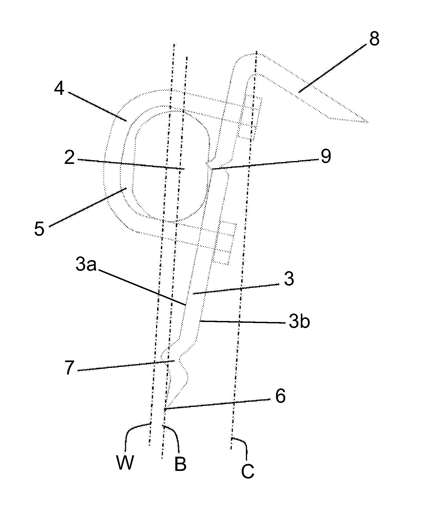
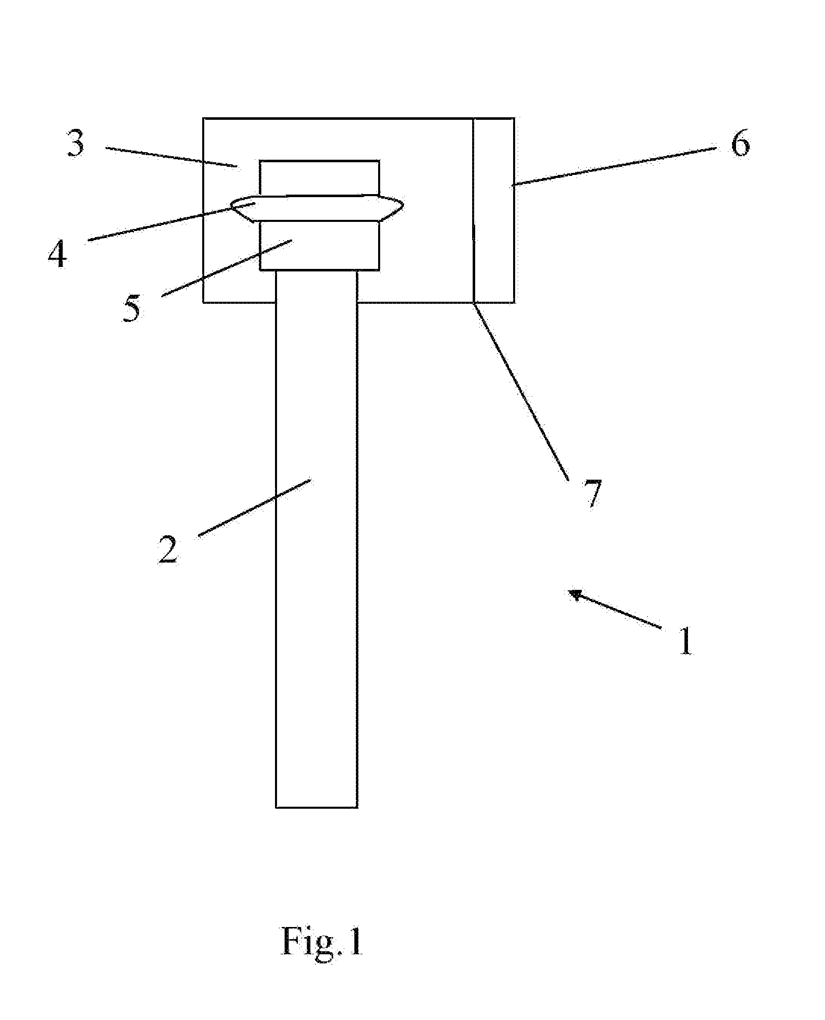
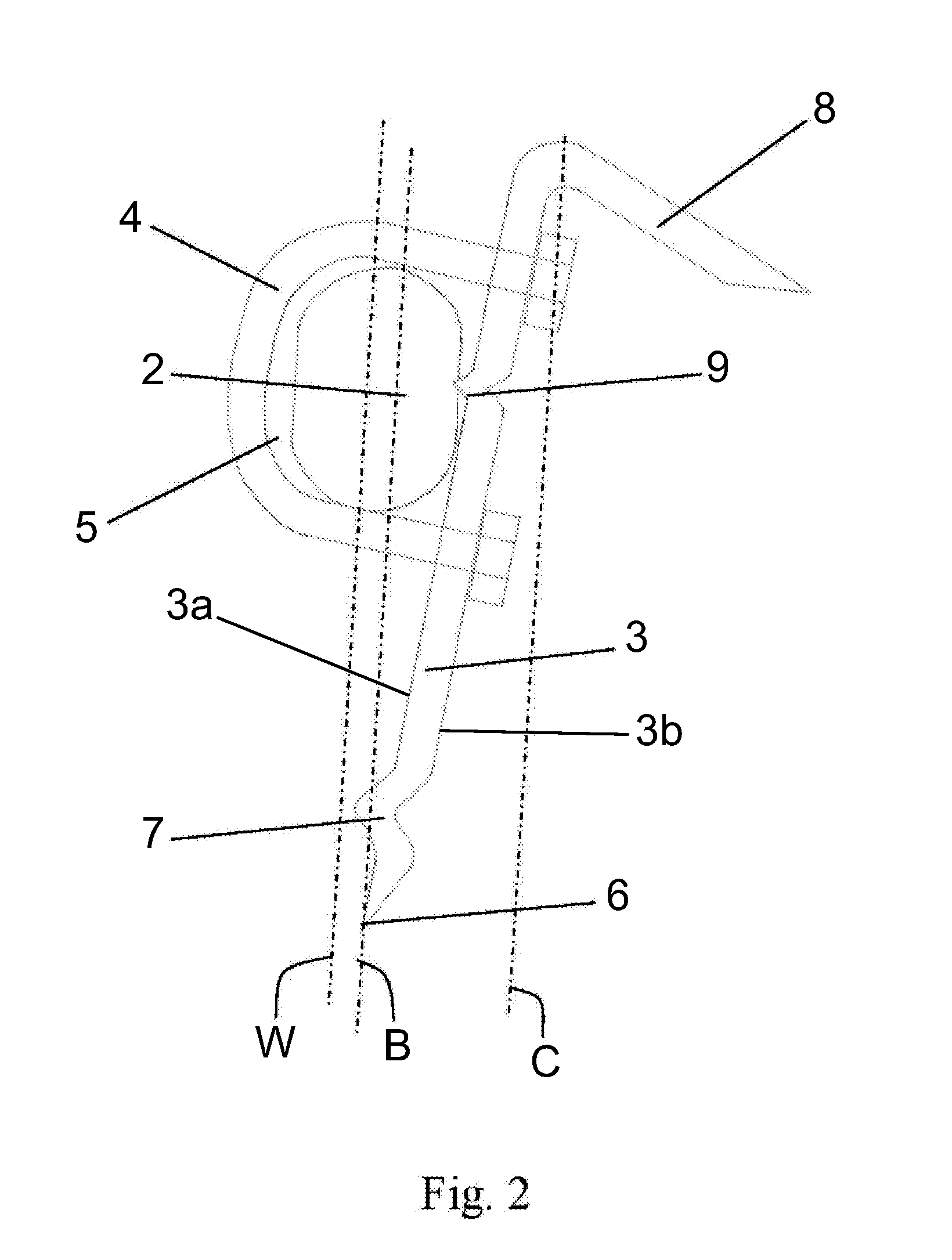
[0030]The FIG. 1 shows an axe 1 that comprises a handle 2 which the handle 2 is attached to the blade 3 with a mounting arrangement 4. The mounting arrangement 4 may also be other than shown in the figure, for example a bolt or several bolts going through the handle and the blade. In this embodiment of the invention the mounting arrangement 4 is a U-bolt. In this preferred embodiment of the invention the portion of the handle 5 attached to the blade 3 is of a different shape than the rest of the handle 2. The blade 3 has a cutting edge 6, a first stop element 7 and a second stop element (not shown in the figure). The portion of the handle 5 which is of a different shape than the rest of the handle is preferably covered with a plastic material or having a plastic sleeve which protects the handle from wearing. The sleeve or the covering may preferably extend to the lower part of the handle too so that all the parts that may hit the wood when missing the target while splitting the wood will be protected from wearing. The portion of the handle 5 attached to the blade may also be of the same shape than the rest of the handle and still having the sleeve or the covering.
[0031]The FIG. 2 shows a top view of the axe 1 seen in FIG. 1. The blade 3 has a first side 3a and a second side 3b which are connected with a cutting edge 6 of the blade 3 and the first side 3a of the blade 3 is connected to the handle. The axe 1 having a handle 2 where the user keeps his hands while splitting wood. The portion 5 of the handle 2 that is attached to the blade 3 is attached to the first side 3a of the blade 3 with a mounting arrangement 4 and with a fixing point 9. The fixing point 9 is preferably bent from the blade material or there can be a separate fixing means, too, for example a staple or a nail. The mounting arrangement 4 is preferably attached to the blade so that the screw head is embedded to the blade 3 to be at the same level as the blade surface. The blade 3 has a cutting edge 6, a first stop element 7 and a second stop element 8. Both stop elements are bent from the same material as the blade. The second stop element 8 may be equipped with extra weighs. The cutting edge 6 of the blade is sharpened with a milling machine or other suitable machine. The cutting edge 6 can also be saw-edged or saw-toothed. A plastic cover or a sleeve may be placed between the handle and the mounting arrangement to prevent the handle from wearing. When the sleeve is placed to the handle, the sleeve is preferably warm so that it is easier to put on.
[0032]The figure also shows the centre of gravity plane C of the axe where the weight of the axe is distributed. The centre of gravity plane C of the axe is located at a distance from the cutting edge 6 of the blade 3. The position of the centre of gravity plane C of the axe depends on the material of which the axe is made. The blade plane B goes through the cutting edge 6 of the blade 3 and is parallel to the normal working motion plane W. The blade plane B, the normal working motion plane W and the centre of gravity plane C are all considered to be parallel.
[0033]It is apparent to a person skilled in the art that as technology advanced, the basic idea of the invention can be implemented in various ways. The invention and its embodiments are therefore not restricted to the above examples, but they may vary within the scope of the claims.

PUM

no PUM

Description & Claims & Application Information

We can also present the details of the Description, Claims and Application information to help users get a comprehensive understanding of the technical details of the patent, such as background art, summary of invention, brief description of drawings, description of embodiments, and other original content. On the other hand, users can also determine the specific scope of protection of the technology through the list of claims; as well as understand the changes in the life cycle of the technology with the presentation of the patent timeline. Login to view more.

Similar technology patents

Optical system and optical microscope

InactiveUS20060262428A1Small spaceEasy to handleMicroscopesRefractorsOptical microscopeSpherical aberration
Owner:YOKOGAWA ELECTRIC CORP

Classification and recommendation of technical efficacy words

  • Small space
  • Easily take

Apparatus for evaluating biological function

InactiveUS20050080323A1Great reliabilitySmall spaceDiagnostic recording/measuringSensorsImage resolutionDeoxygenated Hemoglobin
Owner:KATO

Barbecue Stove

InactiveUS20080216671A1Small spaceSmall space requiredCooking vesselsEngineering
Owner:LIN ARLO

Quickly soluble film preparations

InactiveUS20050147653A1Rapid absorptionEasily takePharmaceutical non-active ingredientsSheet deliverySoluble FilmHydroxypropylmethyl cellulose
Owner:KYUKYU PHARMA

Heating container

ActiveUS20140261381A1Cost reductionEasily takeExothermal chemical reaction heat productionOther heat production devicesEngineeringShipping container
Owner:DOKDO
Why Eureka
Try Eureka