Reheat burner

Active Publication Date: 2012-02-16
ANSALDO ENERGIA IP UK LTD
View PDF4 Cites 9 Cited by
  • Summary
  • Abstract
  • Description
  • Claims
  • Application Information

AI Technical Summary

Benefits of technology

[0039]In addition, thanks to the particular configuration with lance tip 14 upstream of the high speed area 16 (in the hot gas direction) and housed in the contracting area 18, the hot gases keep accelerating up to a location downstream of the lance tip 14, such that risks that the flame travels upstream of the lance tip 14 and, consequently, causes flashback are reduced; this allows a reduced flashback risk and oil operation with a reduced amount of water.
[0040]After the high speed area 16, the hot gases pass through the diffusion area 17, where their speed decreases and a portion of the kinetic energy is transformed into static pressure. Deceleration allows the hot gases containing fuel that passed through the high speed zone fast (i.e., at a high speed) to reduce their speed, such that they enter the combustion chamber 12 downstream of the burner 1 at a low speed; this allows the fuel to have a sufficient residence time in the combustion chamber 12 to completely and correctly burn and achieve low CO emissions. In addition, since a portion of the kinetic energy in transformed to static pressure, the pressure drop suffered in the vortex generation area 6, in the contr

Problems solved by technology

In addition, high vortex strength and turbulence level reduce the NOx and CO emissions (thanks to the good mixing), but increase the pressure drop (thus they reduce efficiency and achievable power).
Such an increase causes the delicate equilibrium among all the parameters to be missed, such that a reheat burner operating with hot gases having a higher temperature than the design temperature may have flashback, NOx, CO emissions, water consumption and pressure drop problems.

Method used


Image

  • Reheat burner
  • Reheat burner
  • Reheat burner

Examples


Embodiment Construction

[0024]With reference to the figures, a reheat burner is illustrated; in the following, like reference numerals designate identical or corresponding parts throughout the several views.

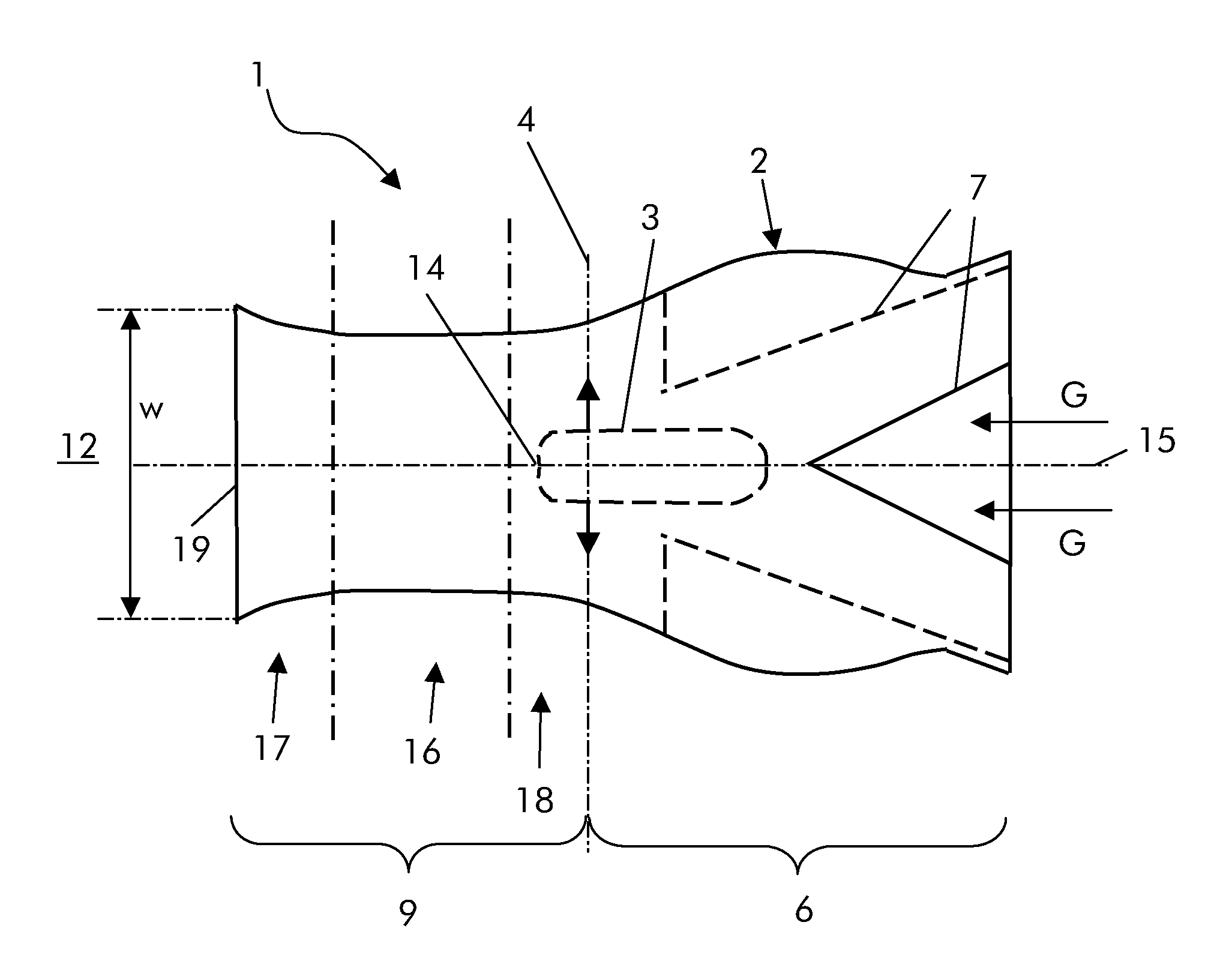
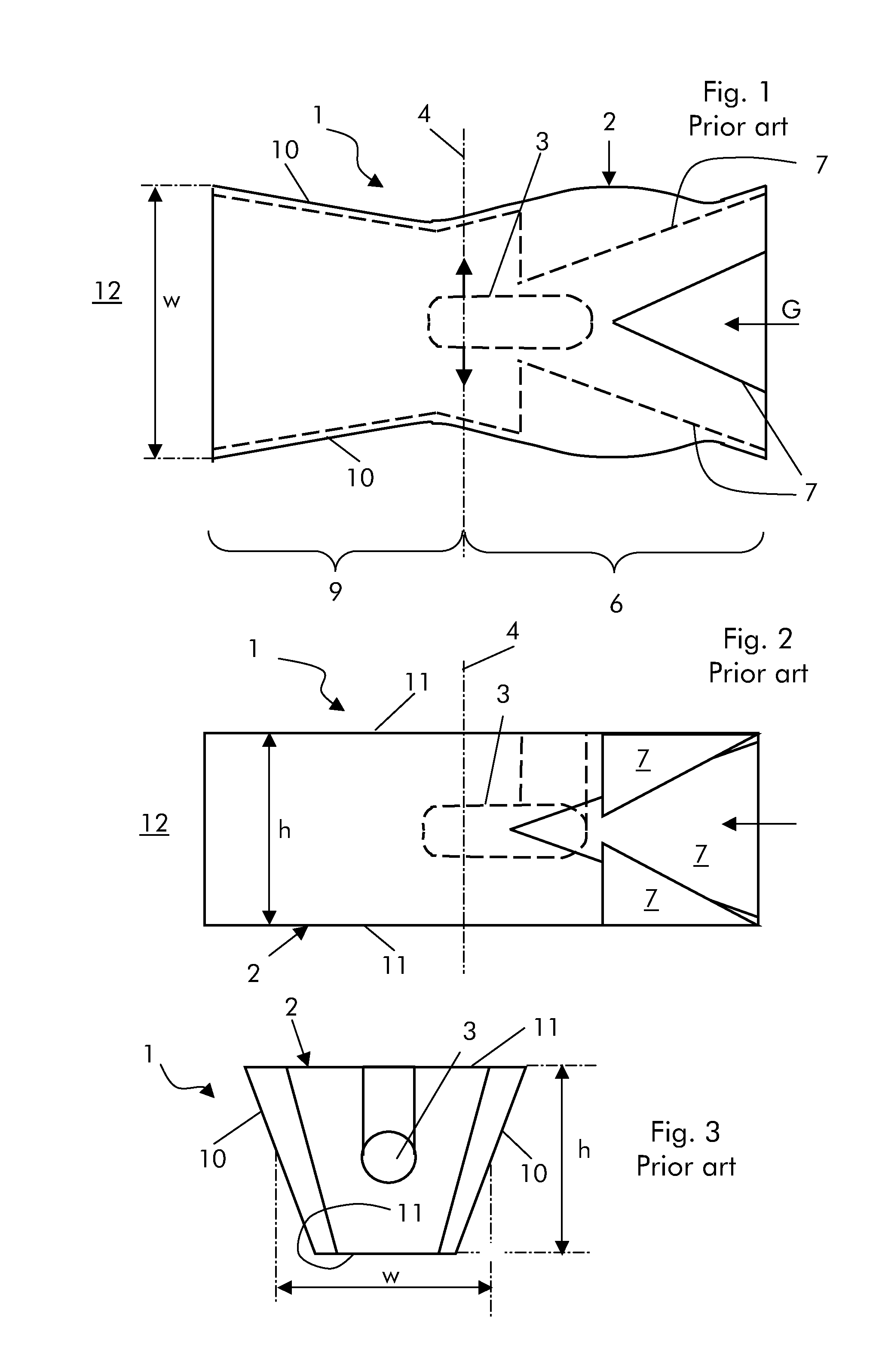
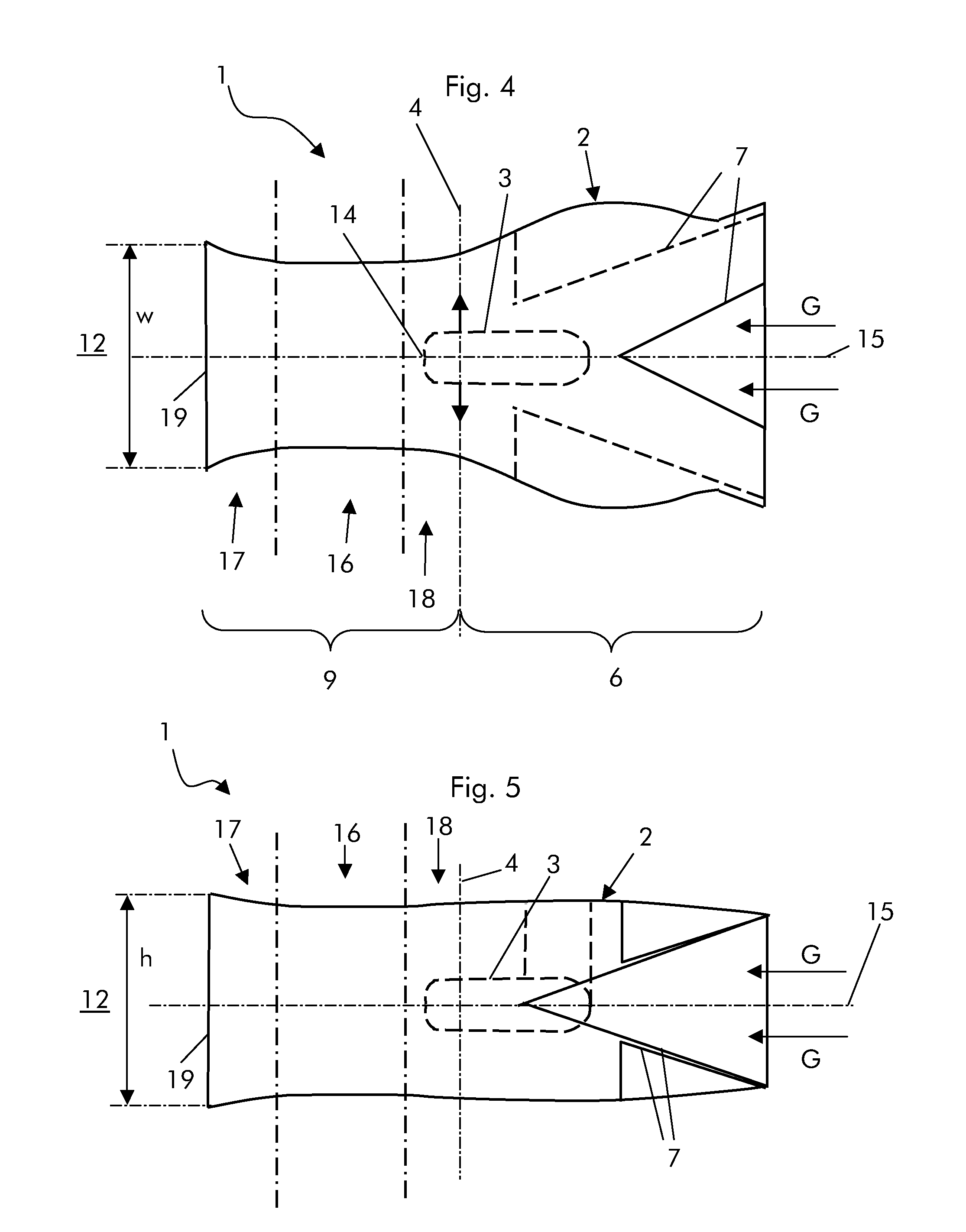
[0025]The reheat burner 1 includes a channel 2 with a quadrangular, square or trapezoidal cross section.

[0026]A lance 3 protrudes into the channel 2 to inject a fuel over an injection plane 4 perpendicular to a channel longitudinal axis 15.

[0027]The channel 2 and lance 3 define a vortex generation zone 6 upstream of the injection plane 4 and a mixing zone 9 downstream of the injection plane 4 in the hot gas G direction.

[0028]The mixing zone 9 includes a high speed area 16 with a constant cross section, and a diffusion area 17 with a flared cross section downstream of the high speed area 16 in the hot gas G direction.

[0029]The high speed area 16 has the smallest cross section of the burner 1.

[0030]In addition, upstream of the high speed area 16, the mixing zone 9 has a contracting area 18.

[0031]As clearl...


PUM


Abstract

A reheat burner (1) includes a channel (2) with a lance (3) protruding thereinto to inject a fuel over an injection plane (4) perpendicular to a channel longitudinal axis (15). The channel (2) and lance (3) define a vortex generation zone (6) upstream of the injection plane (4) and a mixing zone (9) downstream of the injection plane (4) in the hot gas (G) direction. The mixing zone (9) includes a high speed area (16) with a constant cross section, and a diffusion area (17) with a flared cross section downstream of the high speed area (16) in the hot gas (G) direction.

Description

[0001]This application claims priority under 35 U.S.C. §119 to European Application No. 10172941.6, filed 16 Aug. 2010, the entirety of which is incorporated by reference herein.BACKGROUND[0002]1. Field of Endeavor[0003]The present invention relates to a reheat burner.[0004]2. Brief Description of the Related Art[0005]Sequential combustion gas turbines are known to include a first burner, in which a fuel is injected into a compressed air stream to be combusted generating flue gases that are partially expanded in a high pressure turbine.[0006]The flue gases coming from the high pressure turbine are then fed into a reheat burner, in which a further fuel is injected into the reheat burner to be mixed and combusted in a combustion chamber downstream of it; the flue gases generated are then expanded in a low pressure turbine.[0007]FIGS. 1-3 show a typical example of a traditional reheat burner.[0008]With reference to FIGS. 1-3, traditional burners 1 have a quadrangular channel 2 with a l...

Claims


Application Information

Patent Timeline
IPC IPC(8): F02C1/06F02C7/228
CPCF23D11/402F23D11/408F23D14/64F23R3/20F23R2900/03341F23R3/002F23R3/12
Inventor BUSS, JOHANNESCIANI, ANDREAEROGLU, ADNANBENZ, URSDUSING, MICHAELHUTAPEA, MICHAEL
Owner ANSALDO ENERGIA IP UK LTD
Why Eureka
Try Eureka