Operation control method of fuel cell and operation control apparatus of fuel cell

Active Publication Date: 2016-05-12
TOYOTA JIDOSHA KK
View PDF1 Cites 0 Cited by
  • Summary
  • Abstract
  • Description
  • Claims
  • Application Information

AI Technical Summary

Benefits of technology

The present invention provides an operation control method for a fuel cell system that can efficiently start up the fuel cell in a low-temperature environment and prevent freezing of generated water. The method includes setting a target operation point based on the startup temperature and the present temperature, controlling the flow rate of reaction gas and the output voltage of the fuel cell to achieve the target operation point, and executing a low-efficiency operation to increase waste heat. The method also includes storing an upper-limit value of the output voltage value of the target operation point based on the startup temperature and the present temperature, and setting the target operation point so that the output voltage value becomes equal to or less than the upper-limit value. These methods can improve the efficiency and reliability of the fuel cell system and prevent damage caused by freezing of generated water.

Problems solved by technology

However, the inventors of the application find out a new problem in that if the voltage value of the target operation points of the fuel cell during low efficiency operation is high, the amount of water that is generated until the fuel cell heats up and exceed the ice point becomes large, and the waste heat becomes less, because of which the generated water freezes and the diffusion of reaction gas inside the fuel cell declines, resulting in a significant decline in the output stability of the fuel cell.
Moreover, when the present temperature of the fuel cell is the same, but the startup temperature is below the ice point and thus at a relatively low value, the problem of re-freezing also occurs.
According to the operation control method of the fuel cell of this aspect, since the low-efficiency operation is performed by reducing the amount of reaction gas, the amount of waste heat of the fuel cell may be increased.

Method used


Image

  • Operation control method of fuel cell and operation control apparatus of fuel cell
  • Operation control method of fuel cell and operation control apparatus of fuel cell
  • Operation control method of fuel cell and operation control apparatus of fuel cell

Examples


embodiment

A. Embodiment

[0024]A1. System Configuration:

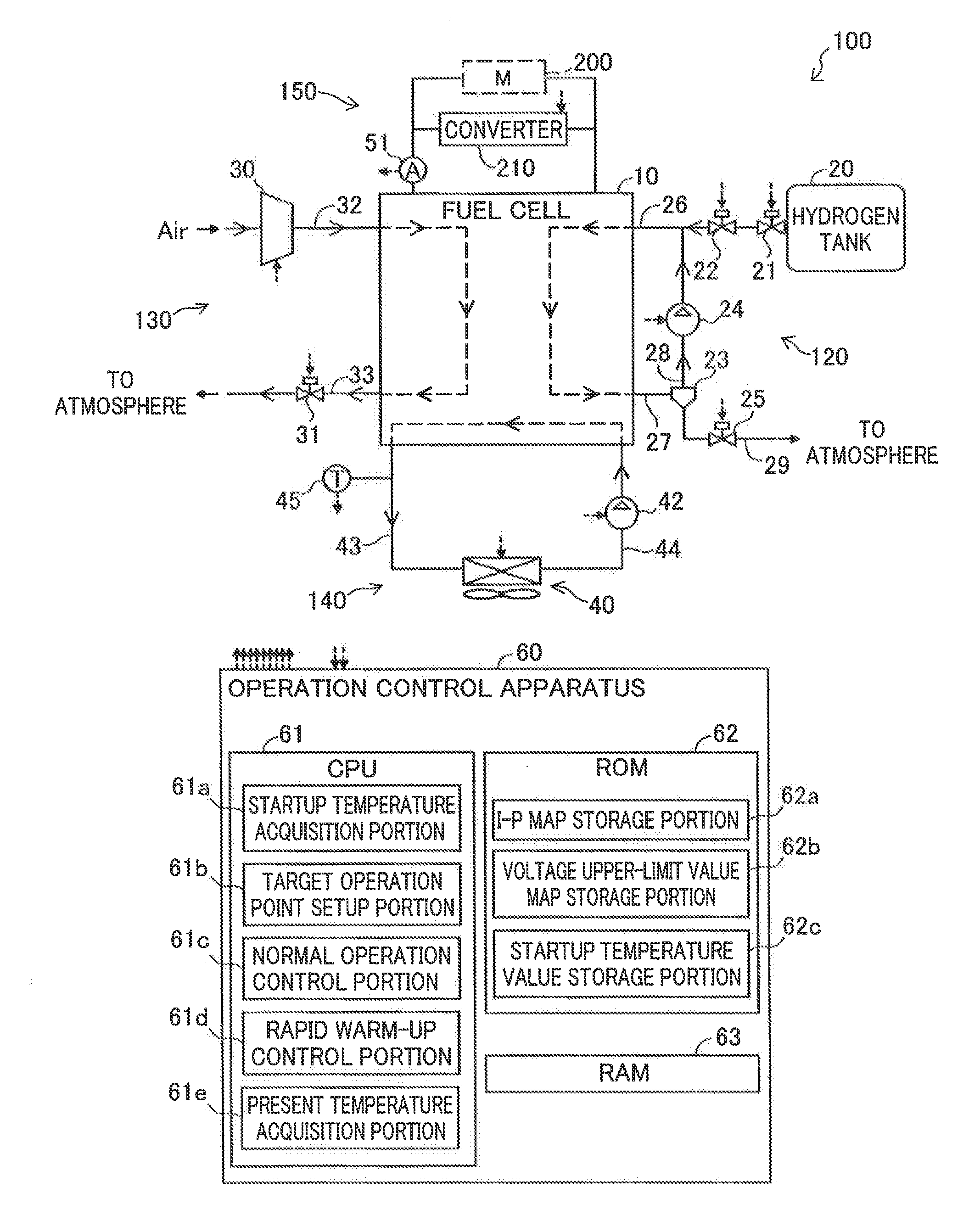
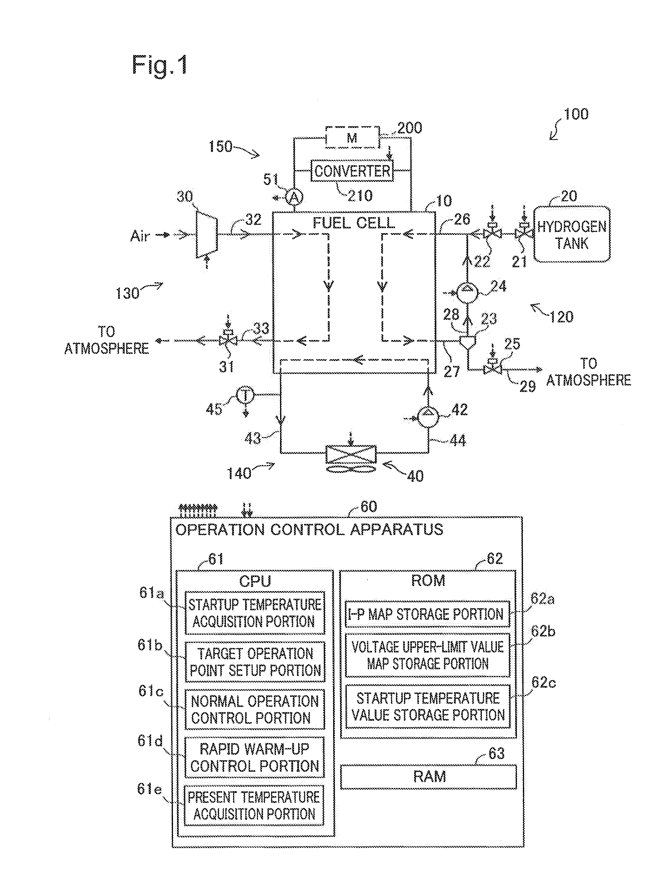
[0025]FIG. 1 is a block diagram showing a schematic configuration of a fuel cell system in which an operation control method of a fuel cell is applied as a first embodiment of the invention. In the present embodiment, the fuel cell system 100 is used as a system for supplying the drive power mounted on a fuel cell vehicle. The fuel cell system 100 includes a fuel cell 10, a fuel gas supply and discharge system 120, an oxidizing gas supply and discharge system 130, a cooling medium circulation system 140, a power supply system 150, and an operation control apparatus 60.

[0026]The fuel cell 10 is a so-called polymer electrolyte fuel cell, which includes a plurality of unit cells stacked along a predetermined direction, a pair of current collecting plates that function as integrated electrodes, and a pair of end plates arranged at the outer side of both ends of a fuel cell stack in order to maintain the stacking condition of the fuel cell stac...


PUM


Abstract

The operation control method of a fuel cell includes acquiring a startup temperature of the fuel cell; acquiring a present temperature of the fuel cell; setting a present target operation point of the fuel cell that is identified by an output voltage value and an output current value based on the startup temperature, or based on the startup temperature and the present temperature; controlling at least one of the flow of the reaction gas supplied to the fuel cell, and an output voltage of the fuel cell so that the operation point of the fuel cell becomes the target operation point, and setting the target operation point includes a process of setting an operation point having a low output voltage value as the target operation point when the startup temperature is low as compared to the case when the startup temperature is high, if the present temperature is the same.

Description

CROSS-REFERENCE TO RELATED APPLICATIONS[0001]The present application claims the priority based on the Japanese Patent Application No. 2014-227684 filed on Nov. 10, 2014, the entirety of disclosure of which is hereby incorporated by reference into this application.BACKGROUND[0002]1. Field[0003]The present invention relates to operation control of a fuel cell.[0004]2. Related Art[0005]A technology has been proposed by which in order to improve stability during startup of a fuel cell in a low-temperature environment such as below the ice point, the waste heat is increased by operating the fuel cell at a lower efficiency than during normal operation, and the fuel cell is heated up in a short period of time. In the fuel cell system according to JP2010-186599A, the volume of the remaining water in the fuel cell is determined based on the impedance of the fuel cell measured during startup or the amount of scavenging air, and if the volume of the remaining water is high and the temperature ...

Claims


Application Information

Patent Timeline
IPC IPC(8): H01M8/04223H01M8/04858H01M8/04746
CPCH01M8/04268H01M8/04865H01M8/04753B60L58/31B60L58/33B60L58/34H01M8/04029H01M8/04253H01M8/0432H01M8/04701H01M8/04768H01M8/04992H01M8/04373H01M8/0488H01M8/0491Y02E60/50Y02T90/40H01M8/04223H01M8/04298H01M8/04365H01M8/04559H01M8/04589
Inventor NAGANUMA, YOSHIAKITOIDA, MASASHIOGAWA, TOMOHIROMARUO, TSUYOSHI
Owner TOYOTA JIDOSHA KK
Why Eureka
Try Eureka