

Elastic wave apparatus
a technology of elastic wave and apparatus, applied in the direction of electrical apparatus, impedence network, etc., to achieve the effect of suppressing the spurious response of higher-order modes and good filter characteristics
- Summary
- Abstract
- Description
- Claims
- Application Information
AI Technical Summary
Benefits of technology
Problems solved by technology
Method used
Image

Examples
first preferred embodiment
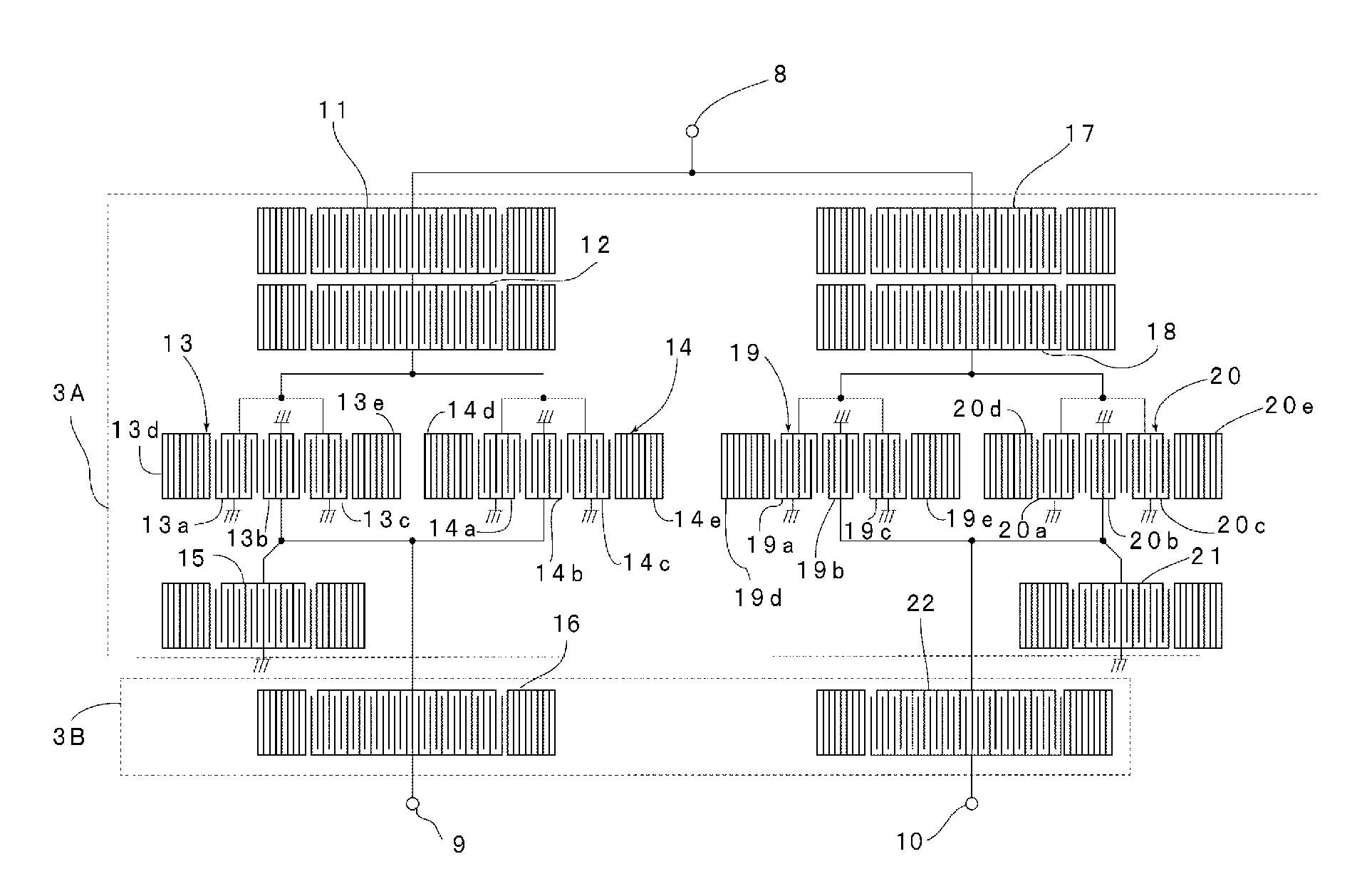
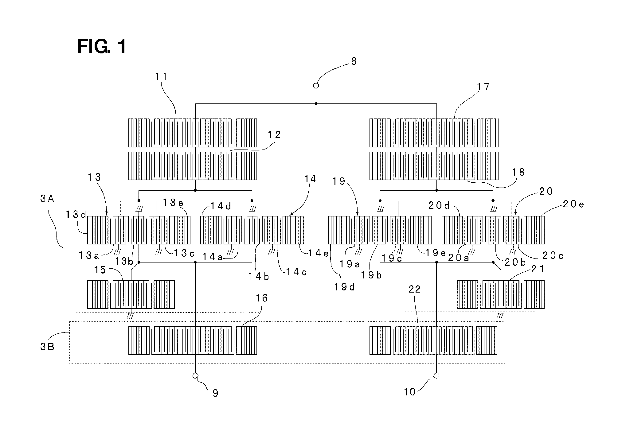
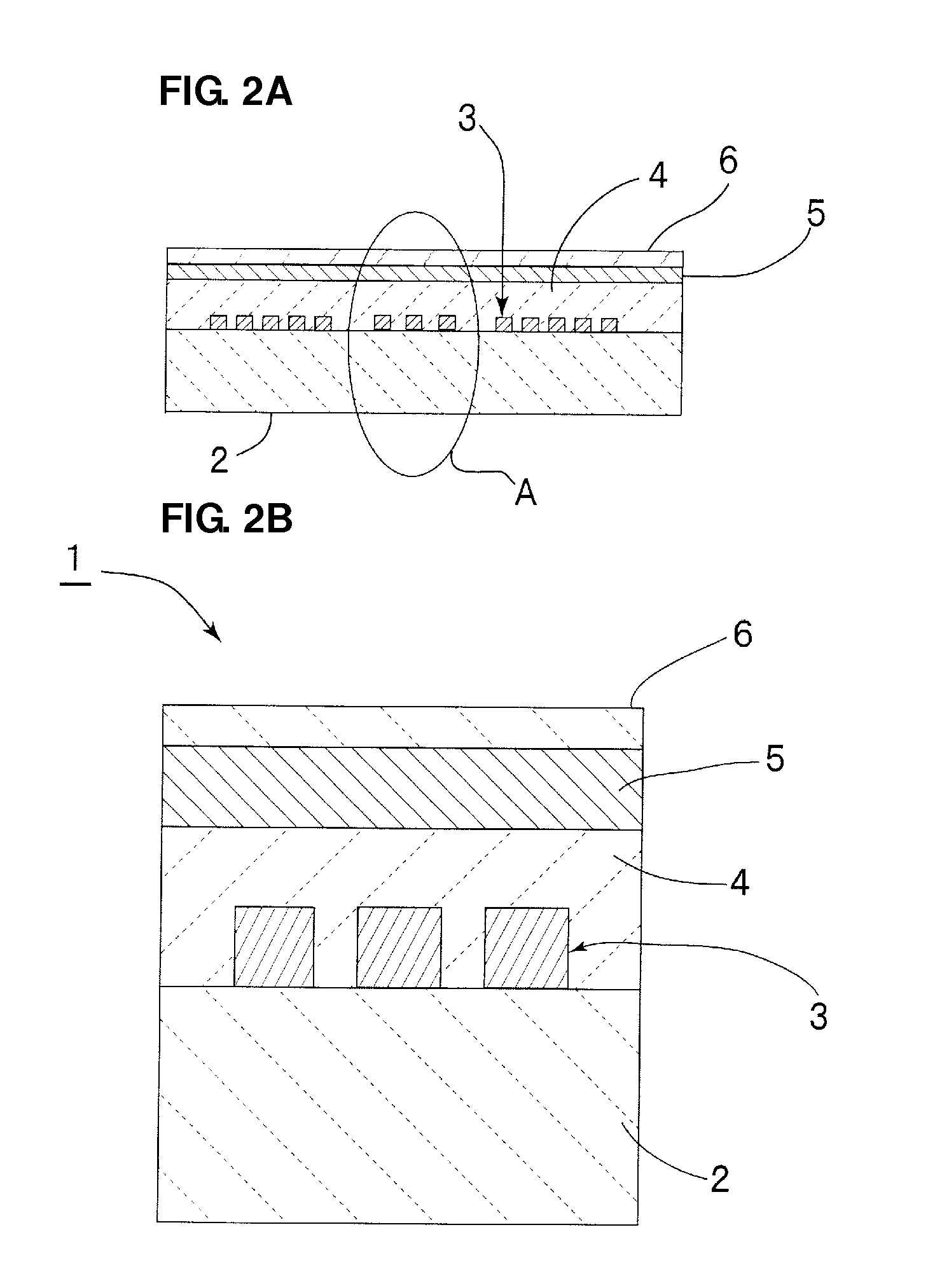
[0031]FIG. 1 is a schematic plan view illustrating the electrode structure of a boundary acoustic wave apparatus that is an elastic wave apparatus according to the first preferred embodiment of the present invention. FIG. 2A is a schematic partial front cross-sectional view of the boundary acoustic wave apparatus. FIG. 2B is an enlarged front cross-sectional view in which a portion represented by an ellipse A in FIG. 2A is enlarged.
[0032]As illustrated in FIGS. 2A and 2B, a boundary acoustic wave apparatus 1 includes a piezoelectric substrate 2. In this preferred embodiment, the piezoelectric substrate 2 is preferably made of a LiNbO3 monocrystal substrate having an Euler angle (0°, 115°, ψ), for example. An electrode structure 3 is provided on the piezoelectric substrate 2. The electrode structure 3 is illustrated in the schematic plan view in FIG. 1. A first dielectric layer 4 is arranged to cover the electrode structure 3. In this preferred embodiment, the first dielectric layer ...
second preferred embodiment
[0086]The difference between the second preferred embodiment of the present invention and the first preferred embodiment is in the setting of wavelengths determined by pitches in IDTS in the fourth boundary acoustic wave resonator 16 and the eighth boundary acoustic wave resonator 22.
[0087]That is, in the second preferred embodiment, the wavelength of the fourth boundary acoustic wave resonator 16 is preferably set to about 1.447 μm, for example, and the wavelength of the eighth boundary acoustic wave resonator 22 is preferably set to about 1.423 μm, for example. Accordingly, since the wavelengths of the fourth boundary acoustic wave resonator 16 and the eighth boundary acoustic wave resonator 22 are different from each other, the anti-resonant frequencies of these boundary acoustic wave resonators are also different from each other.
[0088]FIG. 7 is a diagram illustrating the transmission characteristics of boundary acoustic wave apparatuses according to the first and second preferre...
third preferred embodiment
[0095]In the first preferred embodiment, the fourth boundary acoustic wave resonator 16 and the eighth boundary acoustic wave resonator 22 that are used to suppress the higher-order mode spurious response are preferably connected in series to the first and second longitudinally coupled resonator-type boundary acoustic wave filter portions 13 and 14 and the third and fourth longitudinally coupled resonator-type boundary acoustic wave filter portions 19 and 20, respectively.
[0096]FIG. 10 is a schematic plan view illustrating the electrode structure of a boundary acoustic wave apparatus according to the third preferred embodiment of the present invention. In a boundary acoustic wave apparatus according to the third preferred embodiment, a fourth boundary acoustic wave resonator 16A and an eighth boundary acoustic wave resonator 22A that are used to suppress the higher-order mode spurious response are preferably connected in parallel to the first and second boundary acoustic wave filter...
PUM
 Abstract
Description
Claims
Application Information