
Transformer and display device using the same

a technology of transformer and display device, applied in the field of transformer, can solve the problems of electrical short circuit of coils connected to an external connection terminal of the switching transformer, and the problem of increasing the intensity of the problem, and achieve the effect of convenient connection

Inactive Publication Date: 2012-02-16
SAMSUNG ELECTRO MECHANICS CO LTD
View PDF3 Cites 25 Cited by
  • Summary
  • Abstract
  • Description
  • Claims
  • Application Information

AI Technical Summary

Benefits of technology

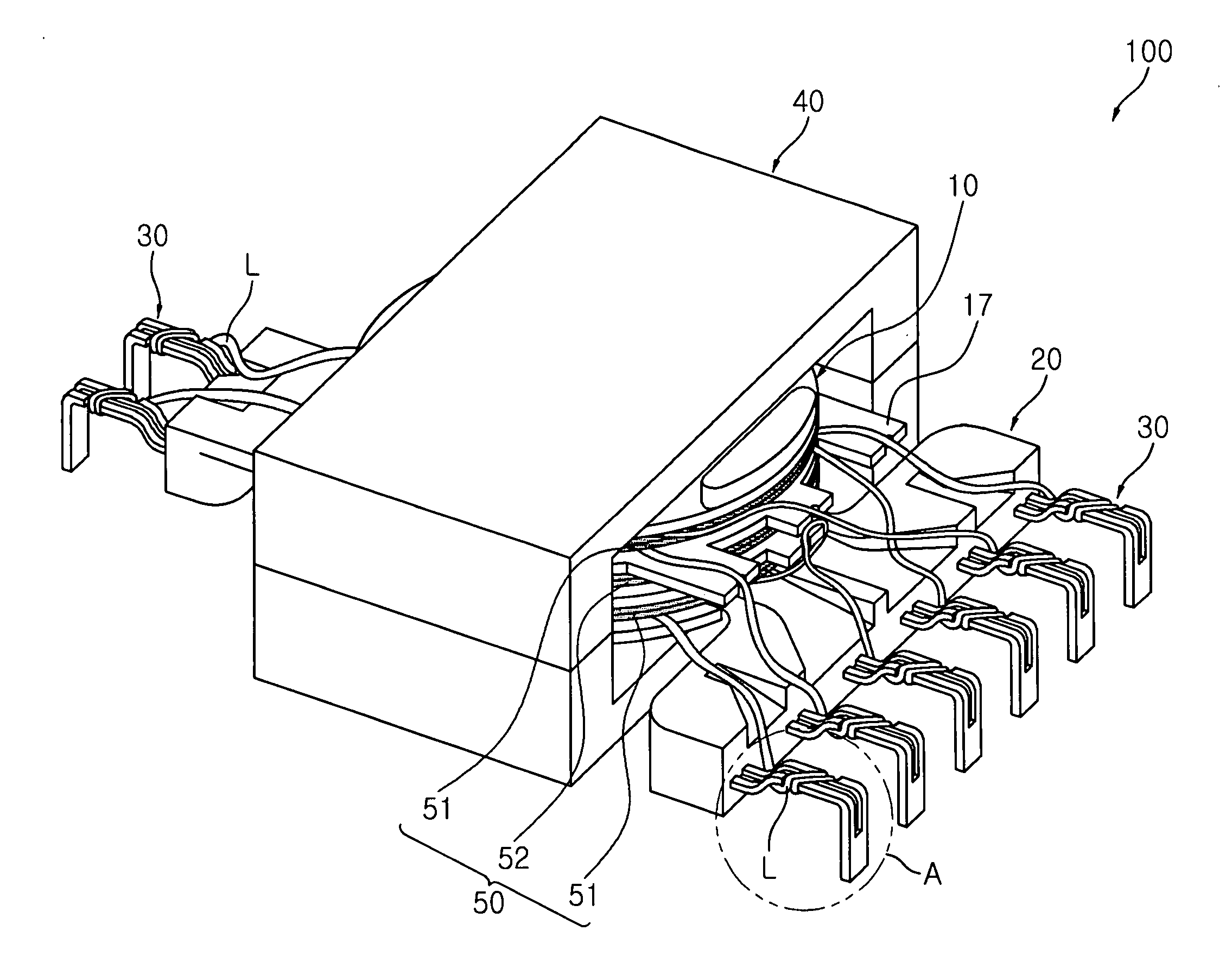
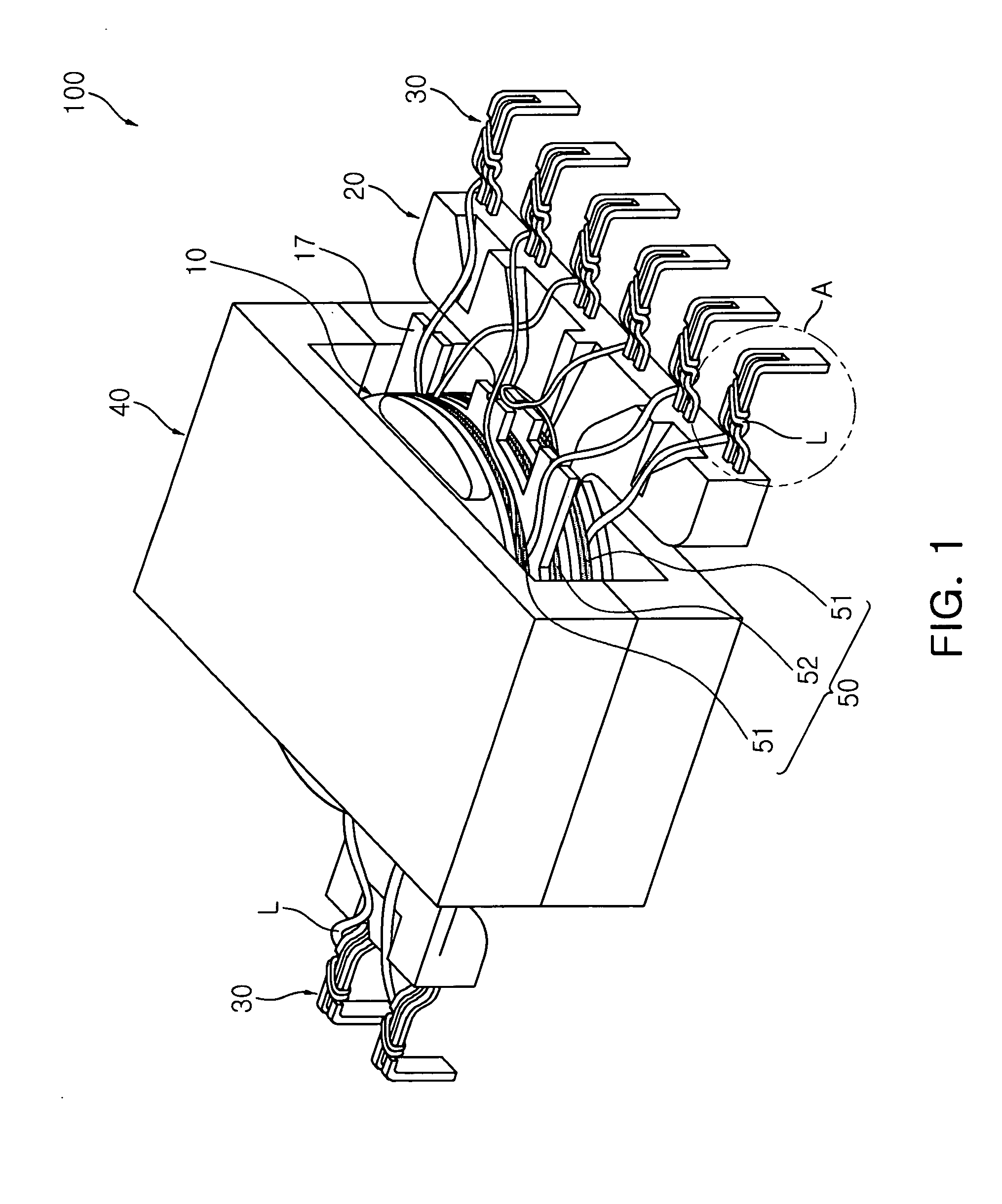
[0009]An aspect of the present invention provides a transformer in which lead wires of coils wound on a small-sized transformer can be easily connected to an external connection terminal without being short-circuited from each other.
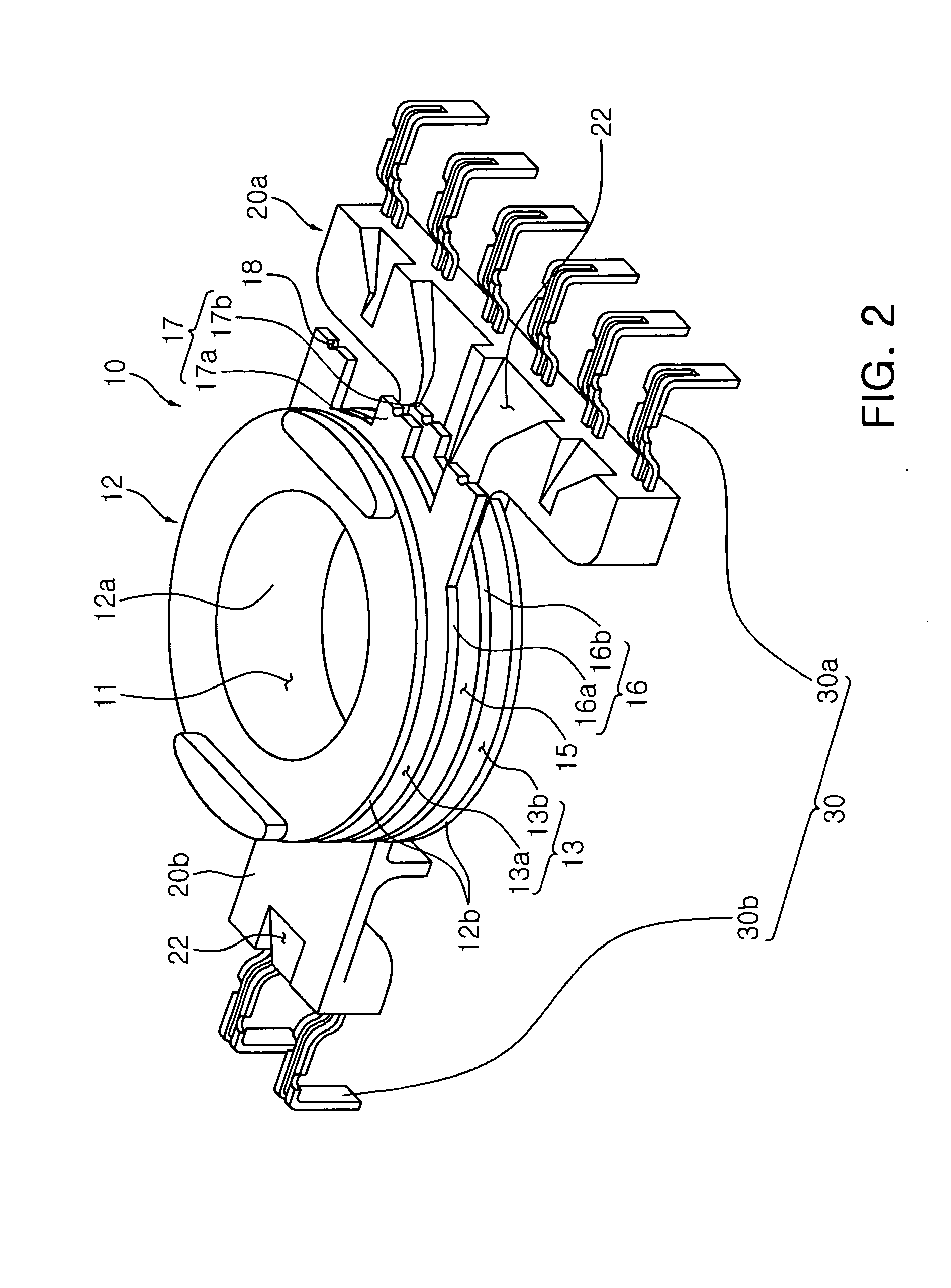
[0036]According to another aspect of the present invention, there is provided a transformer including: a winding unit including a tubular body part having a through-hole formed therein and flange parts protruding outwardly from both ends of the body part; a base provided at an end of at least one flange part and having a plurality of external connection terminals disposed thereon; and at least one coil wound on a space formed by an outer circumferential surface of the body part and one surface of the flange part, wherein lead wires of the coil are distributively disposed on one surface and the other surface of the flange part and connected to the external connection terminals so that the lead wires are prevented from intersecting with each other.

Problems solved by technology

However, as the switching transformer is miniaturized in this manner, lead wires of coils connected to an external connection terminal of the switching transformer are electrically short-circuited.
In addition, in the case in which a plurality of coils are complexdly wound on a single switching transformer, since a plurality of lead wires are connected with the external connection terminal, such a problem may be more intensified.

Method used


Image

  • Transformer and display device using the same
  • Transformer and display device using the same
  • Transformer and display device using the same

Examples


Embodiment Construction

[0052]Prior to a detailed description of the present invention, the terms or words, which are used in the specification and claims to be described below, should not be construed as having typical or dictionary meanings. The terms or words should be construed in conformity with the technical idea of the present invention on the basis of the principle that the inventor(s) can appropriately define terms in order to describe his or her invention in the best way. Embodiments described in the specification and structures illustrated in drawings are merely exemplary embodiments of the present invention. Thus, it is intended that the present invention covers the modifications and variations of this invention, provided they fall within the scope of their equivalents at the time of filing this application.

[0053]Exemplary embodiments of the present invention will be described in detail with reference to the accompanying drawings. The same reference numerals will be used throughout to designate...


PUM


Abstract

There is provided a transformer in which lead wires of a coil are disposed to be separated from each other so as to prevent a short-circuit between the lead wires. The transformer includes a winding unit having a plurality of partitions formed on an outer circumferential surface of a tubular body part; a base provided at one end of the winding unit and including at least one external connection terminal protruding outwardly; a coil wound on a bobbin and having a lead wire connected to the external connection terminal; and a core electromagnetically coupled with the coil to thereby form a magnetic path, wherein the bobbin includes at least one lead wire supporting portion protruding outwardly from the partitions, supporting the lead wire and guiding the lead wire to the external connection terminal.

Description

CROSS-REFERENCE TO RELATED APPLICATIONS[0001]This application claims the priorities of Korean Patent Application Nos. 10-2010-0077581 filed on Aug. 11, 2010 and 10-2011-0060137 filed on Jun. 21, 2011, in the Korean Intellectual Property Office, the disclosures of which are incorporated herein by reference.BACKGROUND OF THE INVENTION[0002]1. Field of the Invention[0003]The present invention relates to a transformer, and more particularly, to a transformer in which lead wires of coils can be disposed to be separated from each other so as to prevent the lead wires of coils from being short-circuited.[0004]2. Description of the Related Art[0005]Various electronic apparatuses, such as a television (TV), a monitor, a personal computer (PC), an office automation (OA) apparatus, and the like, require various kinds of power supply. Therefore, a device that converts general AC power supplied from the outside into power required for each electronic appliance is provided in those electronic app...

Claims


Application Information

Patent Timeline
IPC IPC(8): H01F27/29
CPCH01F27/325H01F2005/022
Inventor KIM, DEUK HOONPARK, GEUN YOUNGSEO, SANG JOONEOM, JAE GENCHEON, MYEONG SIK
Owner SAMSUNG ELECTRO MECHANICS CO LTD
Learn More