
Decreasing Image Acquisition Time for Compressive Imaging Devices

Inactive Publication Date: 2012-02-16
INVIEW TECH CORP
View PDF7 Cites 90 Cited by
  • Summary
  • Abstract
  • Description
  • Claims
  • Application Information

AI Technical Summary

Benefits of technology

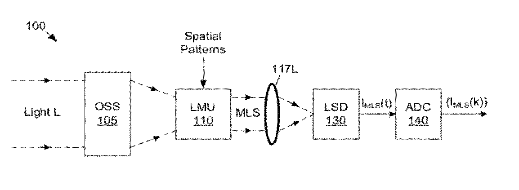
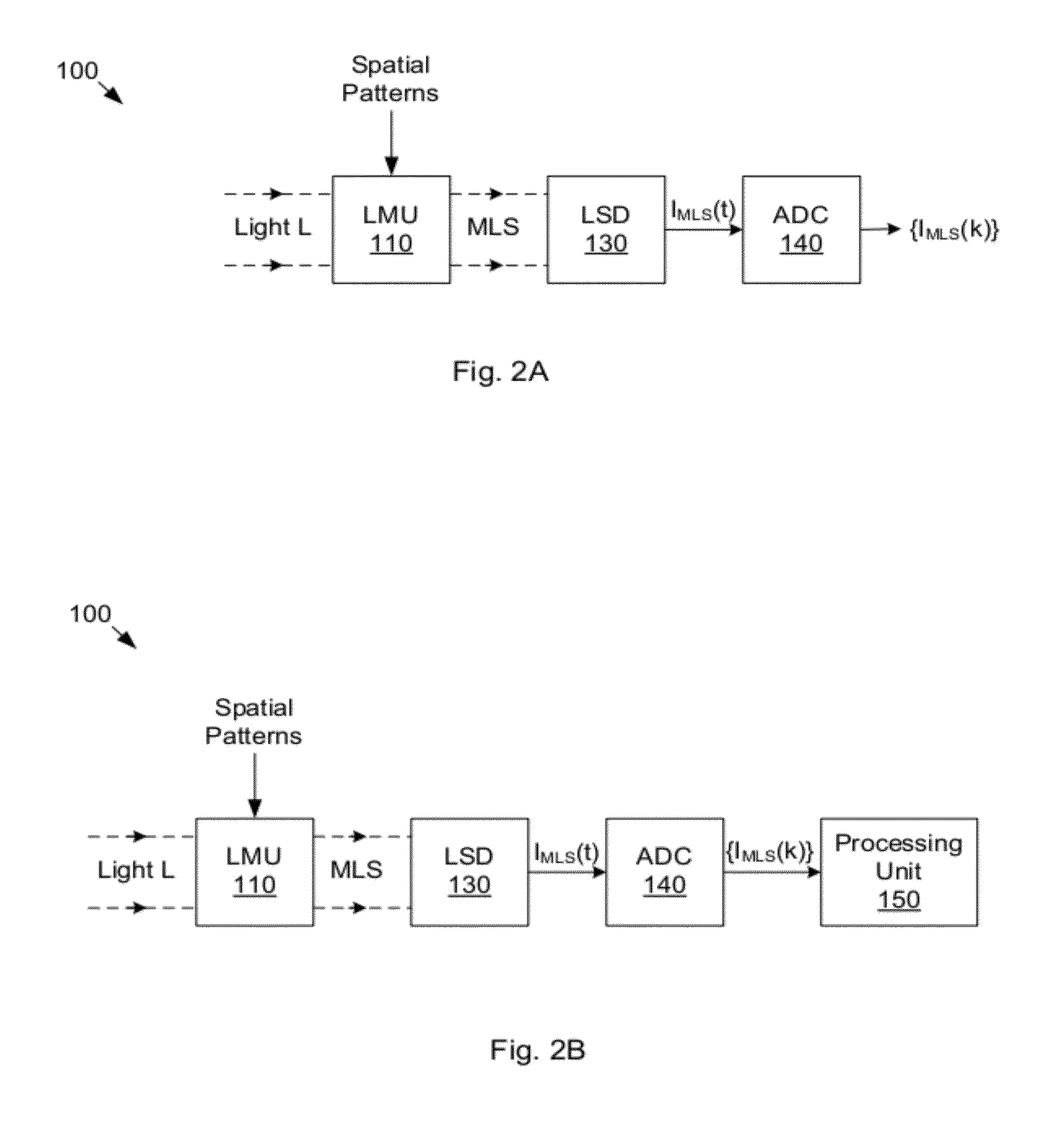
[0020]The sampling subsystem is configured to acquire samples of the electrical signals, preferably in parallel. The samples include sample subsets that correspond respectively to the electrical signals. In other words, each sample subset comprises samples of the respective electrical signal. The sample subsets are usable to reconstruct respective sub-images of a final image that represents the incident light stream. Because the sub-images are smaller than the final image, the number of samples of each electrical signal needed to reconstruct the respective sub-image is significantly smaller than the number of samples a single-pixel camera would have to acquire to reconstruct the final image. Thus, the time required to acquire the compressed data-equivalent of the final image is significantly reduced. In video applications, this means that the imaging system may acquire compressed images at a higher frame rate than a single-pixel camera.

Problems solved by technology

A fundamental problem with any attempt to capture a signal x(t) according to Nyquist theory is the large number of samples that are generated, especially when B (or B−A) is large.
The same problem of overwhelming data volume is experienced when attempting to capture an image according to Nyquist theory.
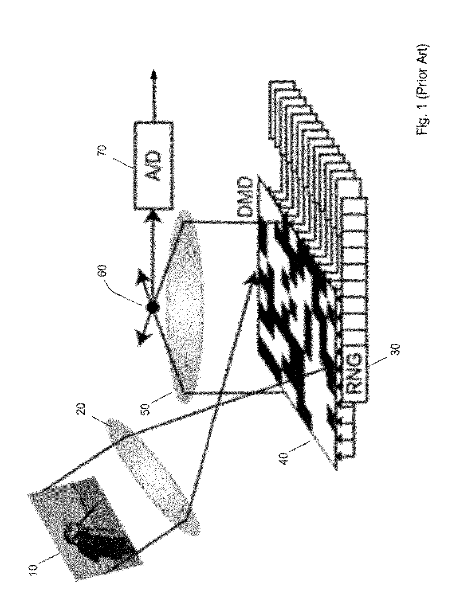
One of the challenges in compressive imaging is acquiring the samples of the signal S(t) fast enough to compete with FPA-based cameras that can operate at video rates.
If N is large, it may be difficult for the above-described compressive-imaging camera to acquire samples of the signal S(t) at a rate sufficiently high to enable video capture, i.e., the capture of encoded representations of N-pixel images at video rates.

Method used


Image

  • Decreasing Image Acquisition Time for Compressive Imaging Devices
  • Decreasing Image Acquisition Time for Compressive Imaging Devices
  • Decreasing Image Acquisition Time for Compressive Imaging Devices

Examples


Embodiment Construction

[0081]The following patent applications provide teachings regarding compressive sensing and compressive imaging:

[0082]U.S. Provisional Application No. 60 / 673,364 entitled “Method and Apparatus for Optical Image Compression,” filed on Apr. 21, 2005;

[0083]U.S. Provisional Application No. 60 / 679,237 entitled “Method and Apparatus for Reconstructing Data from Multiple Sources,” filed on May 10, 2005;

[0084]U.S. Provisional Application No. 60 / 729,983 entitled “Random Filters for Compressive Sampling and Reconstruction,” filed on Oct. 25, 2005;

[0085]U.S. Provisional Application No. 60 / 732,374 entitled “Method and Apparatus for Compressive Sensing for Analog-to-Information Conversion,” filed on Nov. 1, 2005;

[0086]U.S. Provisional Application No. 60 / 735,616 entitled “Method and Apparatus for Distributed Compressed Sensing,” filed on Nov. 10, 2005;

[0087]U.S. Provisional Application No. 60 / 759,394 entitled “Sudocodes: Efficient Compressive Sampling Algorithms for Sparse Signals,” filed on Jan....


PUM


Abstract

Mechanisms for increasing the rate of acquisition of compressed / encoded image representations are disclosed. An imaging system may deliver subsets of a modulated light stream onto respective light sensing devices. The light sensing devices may be sampled in parallel. Samples from each light sensing device may be used to construct a respective sub-image of a final image. The parallelism allows compressed images to be acquired at a higher rate. The number of light sensing devices and / or the number of pixels per image may be selected to achieve a target image acquisition rate. In another embodiment, spatial portions of the incident light stream are separated and delivered to separate light modulators. In yet another embodiment, the incident light stream is split into a plurality of beams, each of which retains the image present in the incident light stream and is delivered to a separate light modulator.

Description

RELATED APPLICATION DATA[0001]This application claims the benefit of priority to U.S. Provisional Application No. 61 / 372,826, filed on Aug. 11, 2010, entitled “Compressive Sensing Systems and Methods”, invented by Richard Baraniuk, Gary Woods, Kevin Kelly, Robert Bridge, Sujoy Chatterjee and Lenore McMackin, which is hereby incorporated by reference in its entirety as though fully and completely set forth herein.[0002]This application is a continuation in part of U.S. application Ser. No. 13 / 193,553, filed on Jul. 28, 2011, invented by Richard Baraniuk, Kevin Kelly, Robert Bridge, Sujoy Chatterjee and Lenore McMackin, titled “Determining Light Level Variation in Compressive Imaging by Injecting Calibration Patterns into Pattern Sequence”, which is hereby incorporated by reference in its entirety as though fully and completely set forth herein.[0003]This application is also a continuation in part of U.S. application Ser. No. 13 / 193,556, filed on Jul. 28, 2011, invented by Richard Bar...

Claims


Application Information

Patent Timeline
IPC IPC(8): H04N5/228H04N5/232H01L27/146G06K9/34
CPCG02B26/0833H04N5/335H04N5/3415H04N25/41H04N25/00
Inventor KELLY, KEVIN F.BARANIUK, RICHARD G.MCMACKIN, LENOREBRIDGE, ROBERT F.CHATTERJEE, SUJOYWESTON, TYLER H.
Owner INVIEW TECH CORP
Learn More