Method for processing uplink signal, base station, and user equipment

a technology of uplink signal and base station, applied in the field of communication technologies, can solve problems such as severe isi of signal receiving

Inactive Publication Date: 2012-02-16
HUAWEI TECH CO LTD
View PDF13 Cites 40 Cited by
  • Summary
  • Abstract
  • Description
  • Claims
  • Application Information

AI Technical Summary

Benefits of technology

[0006]A method for processing an uplink signal, a BS, and a UE are provided in embodiments of the present invention to solve the uplink delay problem without introducing too large overhead.
[0026]When the technical solutions provided in the embodiments of the present invention are used, the UE can use different CP types for different TTIs. Therefore, the uplink delay issue can be solved without introducing too large overhead.

Problems solved by technology

For example, an existing system can use normal CP or extended CP, where the normal CP has limited capability for reducing ISI but has a small overhead, and the extended CP can efficiently reduce the ISI, but has a large overhead.
If the arrival time of the uplink signal at a cell is too much earlier or later than the expected time, signal receiving suffers severe ISI.
However, extended CP may introduce a large overhead.

Method used


Image

  • Method for processing uplink signal, base station, and user equipment
  • Method for processing uplink signal, base station, and user equipment
  • Method for processing uplink signal, base station, and user equipment

Examples


embodiment 1

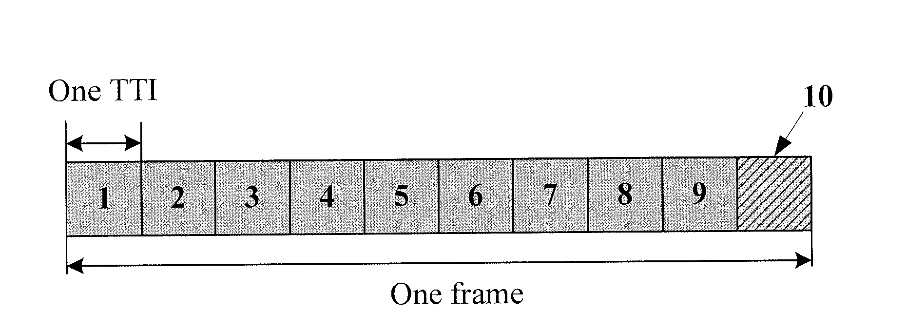
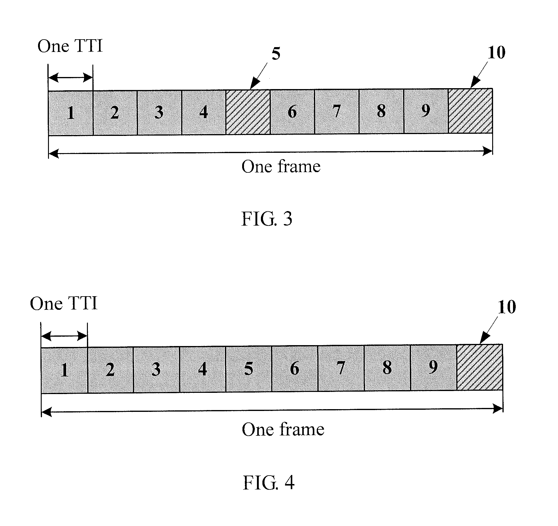
[0051]In this embodiment, the anchor cell can configure a UE for uplink communication, and CP configuration information of configuring the UE can be sent, for example, through configuration signaling, to the UE. The CP configuration information is used to identify a mapping relationship between the TTI and the CP length used by the uplink signal, that is, identify different CP lengths used in different TTIs. In the embodiment, two different CP lengths are taken as an example for illustration. The CP lengths can be called a first CP length and a second CP length that are corresponding to a first CP type and a second CP type respectively. The length of the first CP type is larger than that of the second CP type. That is, the first CP length is larger than the second CP length. Then, the CP configuration information may include any of the following information:

[0052]1. Period of the TTI that uses the first CP length

[0053]2. Period of the TTI that uses the second CP length

[0054]3. Numbe...

embodiment 2

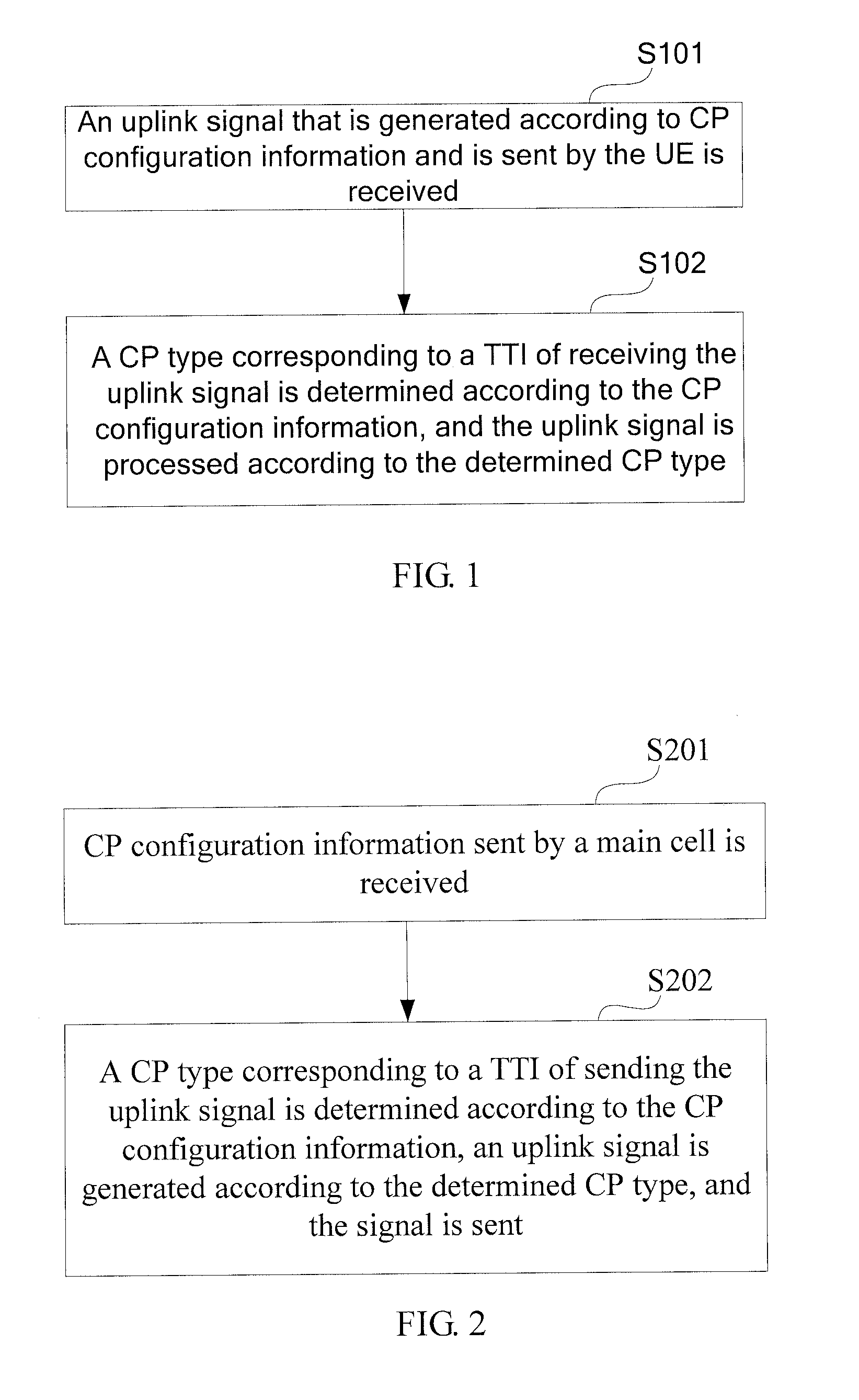
[0096]A UE 700 is provided in an embodiment of the present invention as shown in FIG. 7, including:

[0097]a first receiving module 701, configured to receive an uplink signal that is generated according to CP configuration information and is sent by a UE, where the CP configuration information is used to identify a mapping relationship between a TTI and a CP type used by the uplink signal; and

[0098]a first processing module 702, configured to determine, according to the CP configuration information, a CP type corresponding to the TTI of receiving the uplink signal, and processing the uplink signal according to the determined CP type.

[0099]For the BS 700, regardless of the CP type used by the UE to generate the uplink signal, the BS 700 can determine the CP type used by the received uplink signal according to the CP configuration information that is the same as that of the UE, thereby correctly processing the uplink signal. It can be seen that the UE can use different CP types in diff...


PUM


Abstract

A method for processing an uplink signal, a BS, and a UE are provided. The method includes: receiving an uplink signal that is generated according to CP configuration information and is sent by a UE, where the CP configuration information is used to identify a mapping relationship between a TTI and a CP type that is used by the uplink signal; and determining, according to the CP configuration information, a CP type corresponding to a TTI of receiving the uplink signal, and processing the uplink signal according to the determined CP type. The UE can use different CP types in the case of different TTIs. Therefore, the technical solutions provided in embodiments of the present invention provide support for solving the uplink delay without introducing too large overhead.

Description

CROSS-REFERENCE TO RELATED APPLICATION[0001]This application is a continuation of International Application No. PCT / CN2009 / 071589, filed on Apr. 30, 2009, which is hereby incorporated by reference in this entirety.FIELD OF THE INVENTION[0002]The present invention relates to the field of communications technologies, and in particular, to a method for processing an uplink signal, a base station (BS), and a user equipment (UE).BACKGROUND OF THE INVENTION[0003]At present, certain systems generally use CP (Cyclic Prefix, Cyclic Prefix) to reduce ISI (Inter-Symbol-Interference, Inter-Symbol-Interference). For example, an existing system can use normal CP or extended CP, where the normal CP has limited capability for reducing ISI but has a small overhead, and the extended CP can efficiently reduce the ISI, but has a large overhead.[0004]In the future mobile communication system, the CoMP (Coordinated Multi-point transmission, Coordinated Multi-point transmission) technology is introduced. ...

Claims


Application Information

Patent Timeline
Patent Type & Authority Applications(United States)
IPC IPC(8): H04W72/04H04W24/00H04W4/00
CPCH04L1/1893H04L5/0007H04L5/0035H04L5/0053H04L27/2607H04L2001/0092
Inventor ZHOU, MINGYUWAN, LEISONG, WEIWEI
Owner HUAWEI TECH CO LTD
Why Eureka
Try Eureka