Fiber Electrode for Lithium Secondary Battery, Fabrication Method Therefor, and Lithium Secondary Battery Including Fiber Electrode

a lithium secondary battery and fiber electrode technology, applied in the manufacture of final products, cell components, basic electric elements, etc., can solve the problems of poor reactivity of a mixture of manganese compound and lithium compound, high production cost, and large diameter

Inactive Publication Date: 2012-02-16
NAT INST OF ADVANCED IND SCI & TECH +1
View PDF3 Cites 28 Cited by
  • Summary
  • Abstract
  • Description
  • Claims
  • Application Information

AI Technical Summary

Problems solved by technology

However, in this method, the temperature needs to be as high as 700 to 900° C., resulting in a high production cost.
Accordingly, a sintered body obtained in this method tends to be one in which sintering having occurred among particles is uneven, and also, a resultant particle diameter is large, which is unfavorable.
Moreover, the reactivity of a mixture of a manganese compound and a lithium compound is poor even if a burning process is performed thereon at a high temperature.
Accordingly, a resultant composition tends to have lithium deficiency or oxygen deficiency.
In order to avoid these problems, it is necessary to repeatedly perform the burning process and mechanical crushing, which results in an increase in the production cost.
However, it is difficult to evenly form a thin composite material layer on a positive electrode with a conventional coating method.
Such an electrode has a structure in which the surface area of the electrode is insufficient, and which does not allow an electrolyte solution to easily permeate, and which cannot mitigate a stress that occurs due to expansion / contraction in the volume of the active material.
However, in the case of a carbon electrode, the available current density is low, and the theoretical value of capacity density is 372 mAh / g, which is also low.
Moreover, in the case of a carbon electrode, the fabrication process is complex and the fabrication yield is low.
Thus, there is a drawback of a high fabrication cost.
However, if metal lithium is used as a negative electrode of a lithium secondary battery, a lithium dendrite is formed due to repeating charge-discharge reactions.
This causes short-circuiting between electrodes and destruction of a separator, resulting in a sudden decrease in the charge / discharge cycle efficiency of the lithium secondary battery, and also resulting in a decrease in the safety of the battery.
Thus, in the case of using Sn, the cycle life characteristics are very poor.
Moreover, since Sn acts as a catalyst, there is a problem in that an electrolyte solution is decomposed.
However, if a charge / discharge test is performed with a cutoff voltage of 0-1V (Li potential), a capacity reduction to approximately 300 mAh / g is observed after approximately 50 cycles and the capacity is not constant.
This results in a reduced cycle life.

Method used


Image

  • Fiber Electrode for Lithium Secondary Battery, Fabrication Method Therefor, and Lithium Secondary Battery Including Fiber Electrode
  • Fiber Electrode for Lithium Secondary Battery, Fabrication Method Therefor, and Lithium Secondary Battery Including Fiber Electrode
  • Fiber Electrode for Lithium Secondary Battery, Fabrication Method Therefor, and Lithium Secondary Battery Including Fiber Electrode

Examples


fabrication example 1

Electrodeposition Method

Mn3O4 / Carbon Fiber

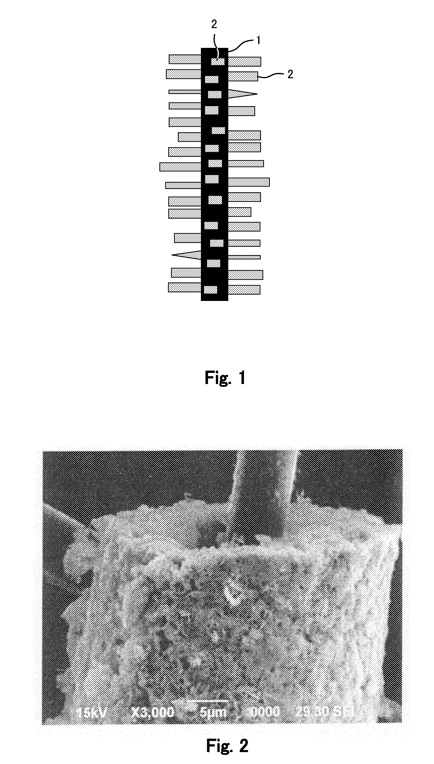
[0210]Here, an Mn(NO3)2 solution (0.3 mol / liter) was used for an electrodeposition bath; a carbon fiber (having a diameter of 6 μm) was used for an electrode acting as a working electrode; and a platinum foil was used for its counter electrode. Electrodeposition was performed under the condition of a constant current density of 50 mA / cm2 for 10 minutes. Thereafter, the electrode was washed with water and then dried under an air atmosphere at a temperature of 100° C. for 24 hours or longer. In this manner, the electrode of which the carbon fiber is coated with Mn3O4 was obtained. It should be noted that only being coated with Mn3O4 does not allow the electrode to function as a positive electrode. FIG. 2 shows an SEM photograph of the electrode in Fabrication Example 1.

fabrication example 2

Electrodeposition Method

NiO / Carbon Fiber

[0211]Here, an Ni(NO3)2 solution (0.3 mol / liter) was used for an electrodeposition bath; a carbon fiber (having a diameter of 6 μm) was used for an electrode acting as a working electrode; and a platinum foil was used for its counter electrode. Electrodeposition was performed under the condition of a constant current density of 50 mA / cm2 for 30 minutes. Thereafter, the electrode was washed with water and then dried under an air atmosphere at a temperature of 130° C. for 24 hours or longer. In this manner, the electrode of which the carbon fiber is coated with NiO was obtained. It should be noted that only being coated with NiO does not allow the electrode to function as a positive electrode.

fabrication example 3

Electrodeposition Method

Mn3O4+NiO / Carbon Fiber

[0212]In order to perform coating with Mn3O4 and NiO in an electrodeposition method, a mixture of Mn(NO3)2 solution (0.3 mol / liter) and Ni(NO3)2 solution (0.03 mol / liter) was used for an electrodeposition bath; a carbon fiber (having a diameter of 6 μm) was used for an electrode acting as a working electrode, and a platinum foil was used for its counter electrode. Electrodeposition was performed with a constant current density of 50 mA / cm2 for 30 minutes. Thereafter, the electrode was washed with water and then dried under an air atmosphere at a temperature of 130° C. for 24 hours or longer. In this manner, the electrode of which the carbon fiber is coated with Mn3O4 and NiO was obtained. It should be noted that only being coated with Mn3O4 and NiO does not allow the electrode to function as a positive electrode.


PUM

PropertyMeasurementUnit
temperatureaaaaaaaaaa
thicknessaaaaaaaaaa
diameteraaaaaaaaaa

Abstract

Provided is a method for mass manufacturing, at low cost, of a fiber positive electrode for a lithium secondary battery, which has excellent charge/discharge cycle characteristics, and which is capable of charging/discharging with high current density, and a main active material of which is a lithium-doped transition metal oxide. The method includes the steps of: (a) forming a tubular coating of either a transition metal oxide or a transition metal hydroxide on a carbon fiber current collector; and (b) performing, in a lithium ion containing solution in a sealed system under presence of an oxidant or a reductant, heat treatment at 100 to 250° C. on the carbon fiber current collector, on which the tubular coating of either the transition metal oxide or the transition metal hydroxide is formed, to obtain a coating of a lithium-doped transition metal oxide on the carbon fiber current collector. Further provided are: a fiber negative electrode for a lithium secondary battery, which has high current density, high energy density, and excellent charge/discharge cycle characteristics, and which can be fabricated in a relatively easy manner; and a method for fabricating the fiber negative electrode. The fiber negative electrode for a lithium secondary battery includes: (c) a carbon fiber current collector; (d) an outer layer which is a tubular composite layer of a Sn oxide and MXOy formed on the carbon fiber current collector; and (e) an intermediate layer formed of a Sn alloy, which has a lithium occlusion capacity and which is present at an interface between the carbon fiber current collector and the outer layer. The method for fabricating the fiber negative electrode for a lithium secondary battery includes: forming a coating of one of Sn and a Sn alloy, and a coating of at least one kind of metal selected from the group consisting of Fe, Mo, Co, Ni, Cr, Cu, In, Sb, and Bi, on a carbon fiber current collector by an electroplating method; and then performing heat treatment on the carbon fiber current collector under a trace oxygen atmosphere at 350 to 650° C. Moreover, the lithium secondary battery includes: the fiber positive electrode and the fiber negative electrode fabricated in the above methods; and an electrolyte.

Description

TECHNICAL FIELD[0001]The present invention relates to an improved fiber electrode for a lithium secondary battery, in which a battery active material is adhered to the surface of an electron-conductive fibrous material, and relates to an improved method for fabricating such a fiber electrode. Further, the present invention relates to a high-power lithium secondary battery, the high-output characteristics of which are realized as a result of forming the battery by bundling the fiber electrodes together or by laminating the fiber electrodes in a fabric-like manner.BACKGROUND ART[0002]In recent years, portable electronic devices such as laptop PCs, mobile phones, and PDAs are in widespread use. Accordingly, there is a demand for a secondary battery used as a power source of these devices to be small-sized and to have high energy density, in order to allow these devices to be lighter and to become usable for longer hours. Conventionally, nickel-cadmium batteries, nickel-hydrogen batteri...

Claims


Application Information

Patent Timeline
Patent Type & Authority Applications(United States)
IPC IPC(8): H01M4/131C25D7/00C25D3/02H01M4/62C25D5/54
CPCH01M4/131H01M4/1391Y02E60/122H01M4/663H01M4/667H01M4/623Y02E60/10Y02P70/50H01M4/139H01M4/62H01M4/75H01M10/052
Inventor SAKAI, TETSUOYAO, JINHANMUKAI, TAKASHITAKASAKI, TOMOAKITSUTSUMI, KAZUONISHIMURA, KAZUYA
Owner NAT INST OF ADVANCED IND SCI & TECH
Why Eureka
Try Eureka