Eureka AIR delivers breakthrough ideas for toughest innovation challenges, trusted by R&D personnel around the world.

Pressure activated ratcheting valve

Inactive Publication Date: 2012-02-23
SUPERIOR ENERGY SERVICES LLC
View PDF5 Cites 19 Cited by
  • Summary
  • Abstract
  • Description
  • Claims
  • Application Information

AI Technical Summary

Benefits of technology

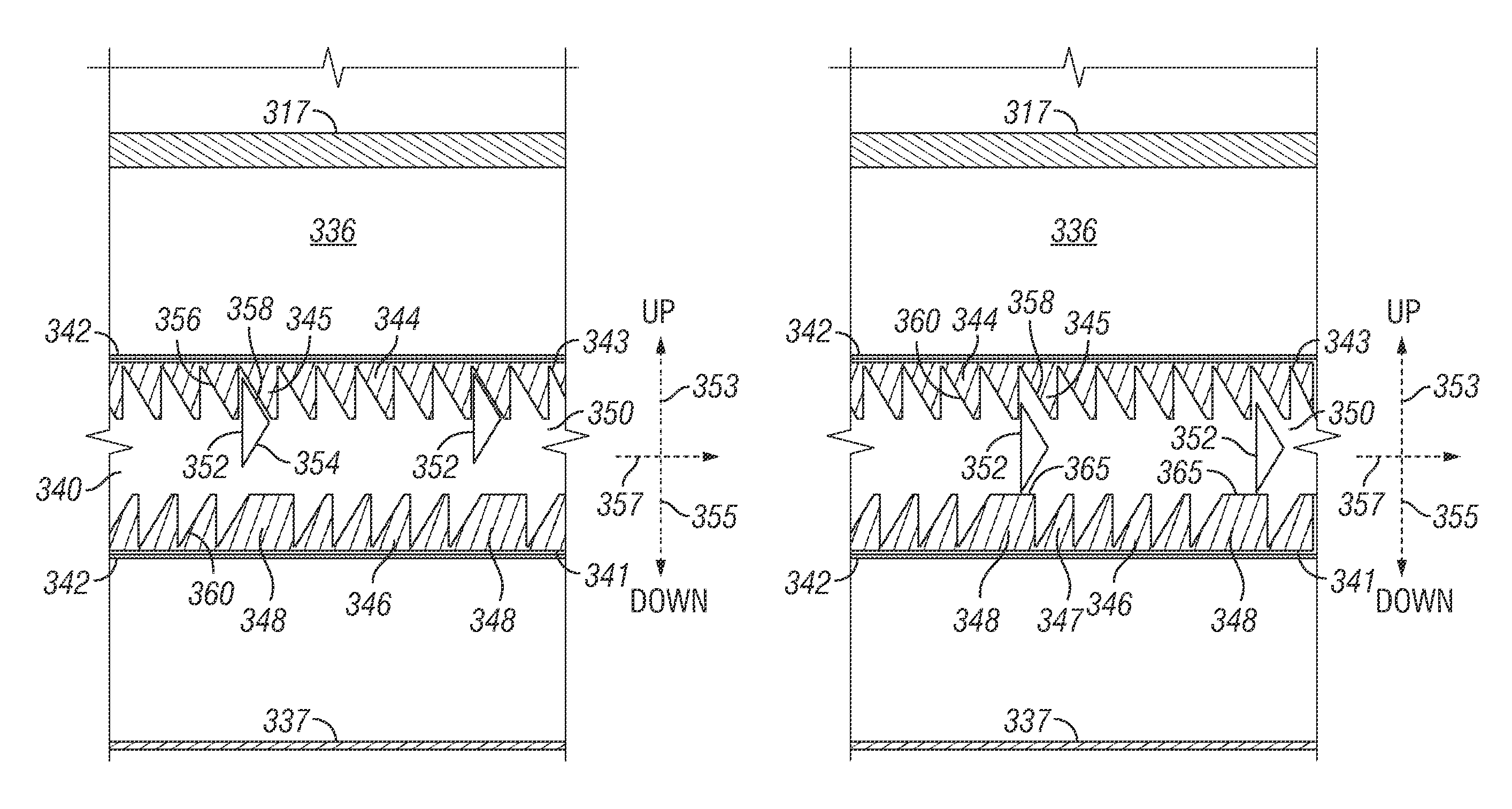
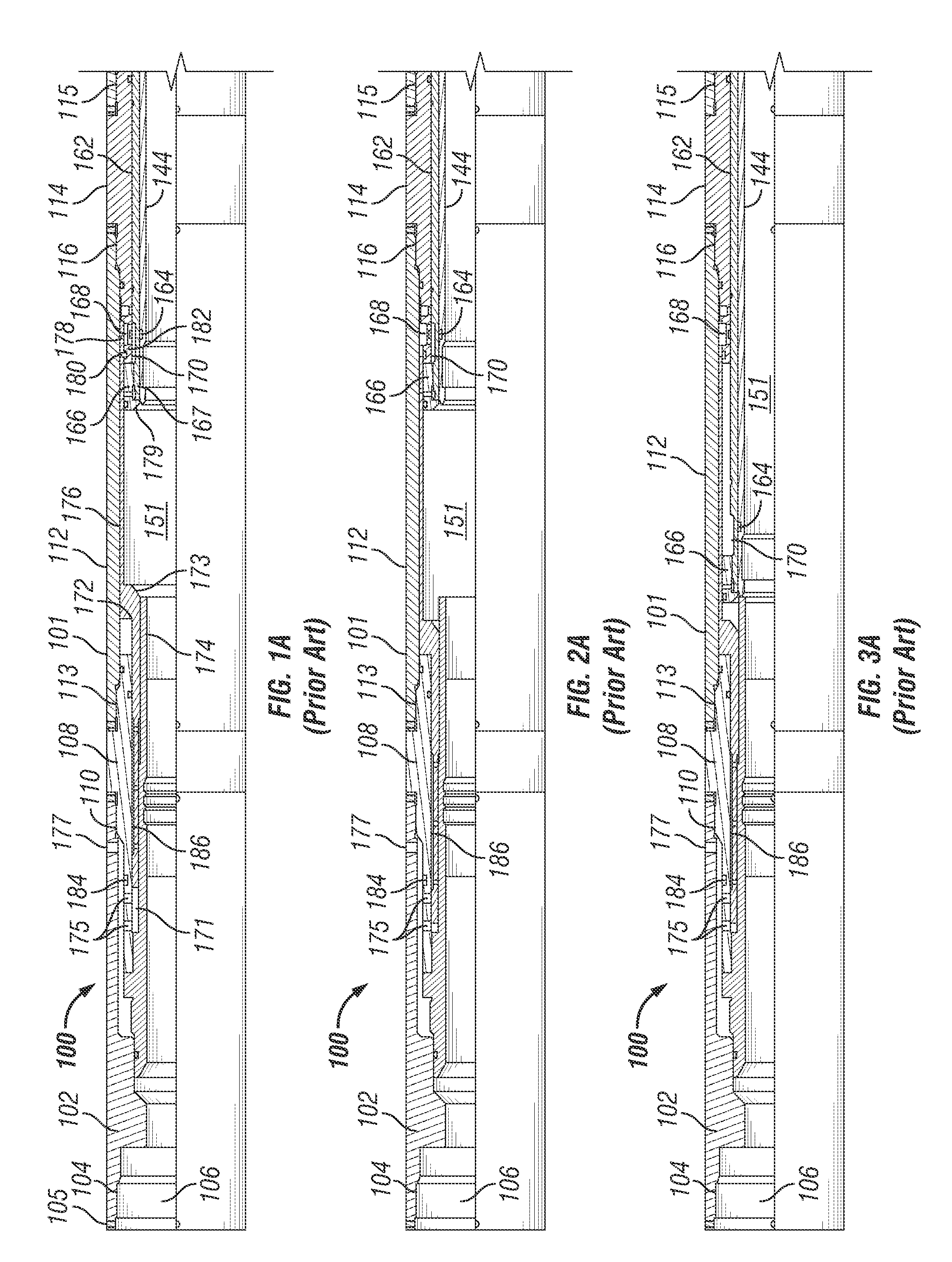
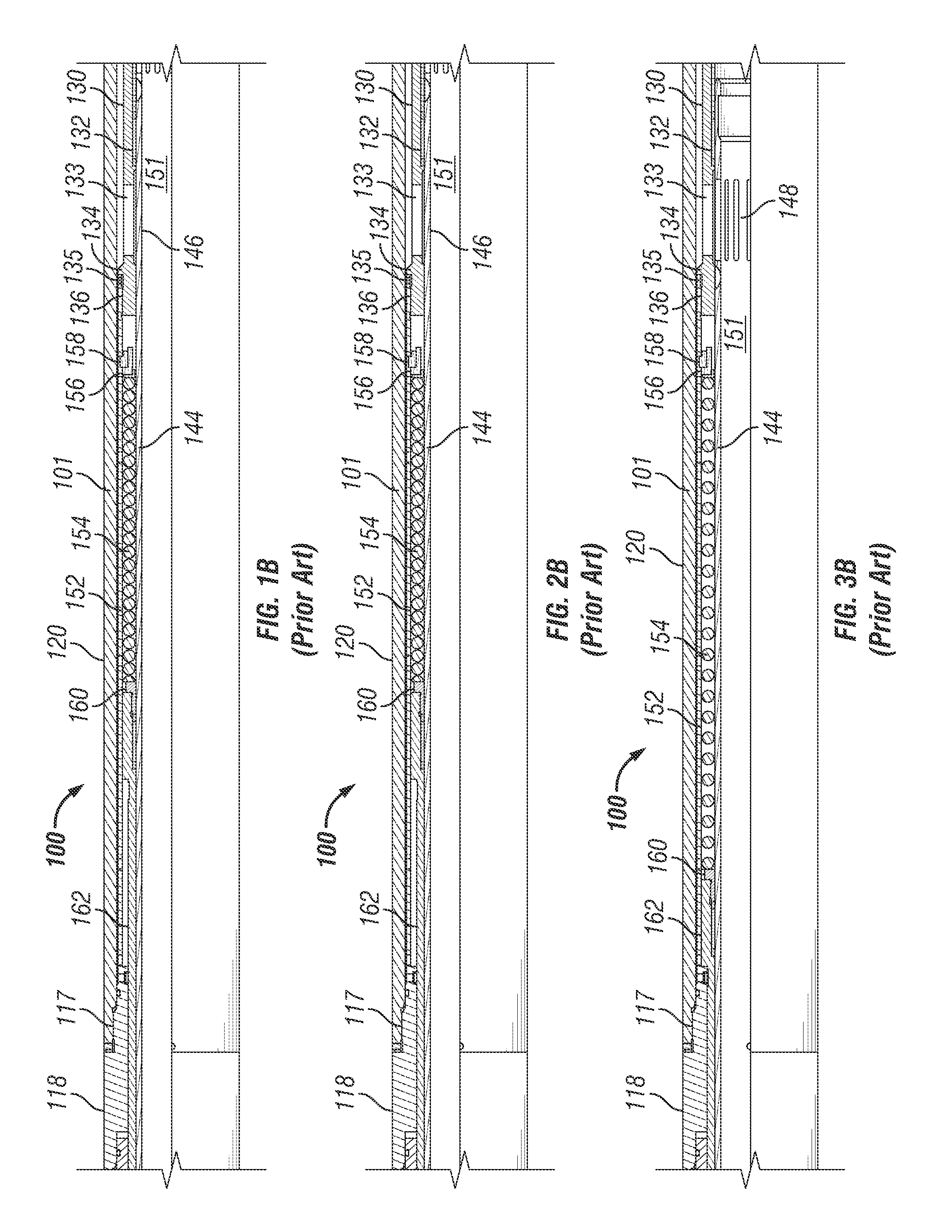
[0007]The present disclosure provides a system which allows an operator to pressurize and bleed a downhole bore without premature opening of a sleeve valve and not requiring the use of a mechanical tool to manually shift the valve. In one embodiment, a double ratchet assembly adapted for moving a valve release sleeve in a first direction and preventing movement of the release sleeve in a second direction opposite the first direction includes a release sleeve having an outer diameter and an outer surface; the release sleeve enclosed in and surrounded by an outer housing, the inner diameter of the outer housing being greater than the outer diameter of the release sleeve and forming an annular void between the outer housing and the release sleeve. An upper housing connector is connected to a proximal end of the outer housing adjacent to the release sleeve; a lower housing connector is connected to a distal end of the outer housing adjacent to the release sleeve. A release piston is disposed within the annular void between the outer housing and the release sleeve, the release piston being moveable in the annular void between t

Problems solved by technology

Locking the sleeve valve closed with a shear pin is both inconvenient and hazardous.
A possibility of over pressurizing the downhole bore and opening the sleeve valve prematurely always exists.
Alternatively, using a shear pin that requires a sufficiently high pressure to avoid premature opening poses a hazard when the downhole bore is pressurized at the high pressure required to shear the pin and unlock the valve.

Method used


Image

  • Pressure activated ratcheting valve
  • Pressure activated ratcheting valve
  • Pressure activated ratcheting valve

Examples


Embodiment Construction

[0032]One or more illustrative embodiments incorporating the disclosure described herein are presented below. Not all features of an actual implementation are necessarily described or shown for the sake of clarity. For example, the various seals, vents, joints and others design details common to oil well equipment are not specifically illustrated or described. It is understood that in the development of an actual embodiment incorporating the present disclosure, numerous implementation-specific decisions must be made to achieve the developer's goals, such as compliance with system-related, business-related, government-related, and other constraints, which vary by implementation and from time to time. While a developer's efforts might be complex and time-consuming, such efforts would be, nevertheless, a routine undertaking for those of ordinary skill in the art having benefit of this disclosure.

[0033]As used within this description, relative and positional terms, such as, but not limi...


PUM


Abstract

A pressure actuated valve is disclosed which includes a plurality of flow openings, and first and second pistons. The first and second pistons are independently actuatable relative to one another, and are releasable coupled to one another by a release sleeve. The pressure actuated valve also includes a closing sleeve that is operatively coupled to the second piston. In an initial position of the second piston, the closing sleeve covers or blocks the plurality of flow openings. The pressure actuated valve includes a ratchet mechanism coupling the release sleeve to the first piston, the ratchet mechanism being adapted to allow movement of the first piston between its initial position and an intermediate position and back to its initial position while allowing the release sleeve to release the second piston after a predetermined number of cycles of movement of the first piston between its initial position and the intermediate position and back to its initial position. Upon release of the second piston by the release sleeve, the second piston, and the closing sleeve, responsive to the urging of a spring, will move to its final position uncovering the plurality of flow openings. The ratchet mechanism allows for the incremental movement of a release sleeve in response to movements of the first piston. The release sleeve is adapted to open the pressure actuated valve upon movement of the release sleeve through a designated distance.

Description

FIELD OF THE DISCLOSURE[0001]The present application relates generally to the field of well completion assemblies for use in a wellbore and, more specifically, to a method and apparatus for opening a pressure actuated valve controlling fluid flow between an annulus and an interior of a production zone within a tubing string in a wellbore.DESCRIPTION OF THE RELATED ART[0002]Mechanical sleeve valves, such as BJ Services Company's family of Multi-Service Valves, are used in subterranean wells to provide zone isolation and bore completion control for completion operations such as gravel packing, spot acidizing and fracturing, killing a well, or directing flow from the casing to the tubing in alternate or selective completion operations. In such operations, the sleeve valve provides fluid communication between the tubing string, such as the inner diameter of the valve, and the outside of the valve, such as a well annulus. Typically, mechanical sleeve valves are opened or closed, such as ...

Claims


Application Information

Patent Timeline
IPC IPC(8): F16K15/00
CPCE21B2034/007E21B34/103E21B2200/06Y10T137/7869
Inventor ROSS, RICHARD J.
Owner SUPERIOR ENERGY SERVICES LLC
Why Eureka
Eureka Blog
Learn More