Laminar flow wing optimized for transonic cruise aircraft

a technology of transonic cruise aircraft and wing sweep, which is applied in the direction of aircraft, wing shapes, transportation and packaging, etc., can solve the problems of inability to achieve extensive nlf for such wing sweep, and inevitable loss of lf coverage, so as to achieve high lift, low wave drag, and extensive laminar flow

Active Publication Date: 2012-02-23
AERION INTPROP MANAGEMENT CORP
View PDF8 Cites 10 Cited by
  • Summary
  • Abstract
  • Description
  • Claims
  • Application Information

AI Technical Summary

Benefits of technology

[0011]The wing thickness to chord ratios may typically vary from outboard of the zone of substantial fuselage influence to the wing tip, such that the average of such ratio along such portion of the span is consistent with the criteria stated in the foregoing. Wing sweep refers to the leading edge of the basic “trapezoidal wing”, or to the minimum leading edge sweep in other cases s

Problems solved by technology

Achieving extensive NLF for such wing sweep is more diff

Method used


Image

  • Laminar flow wing optimized for transonic cruise aircraft
  • Laminar flow wing optimized for transonic cruise aircraft
  • Laminar flow wing optimized for transonic cruise aircraft

Examples


Embodiment Construction

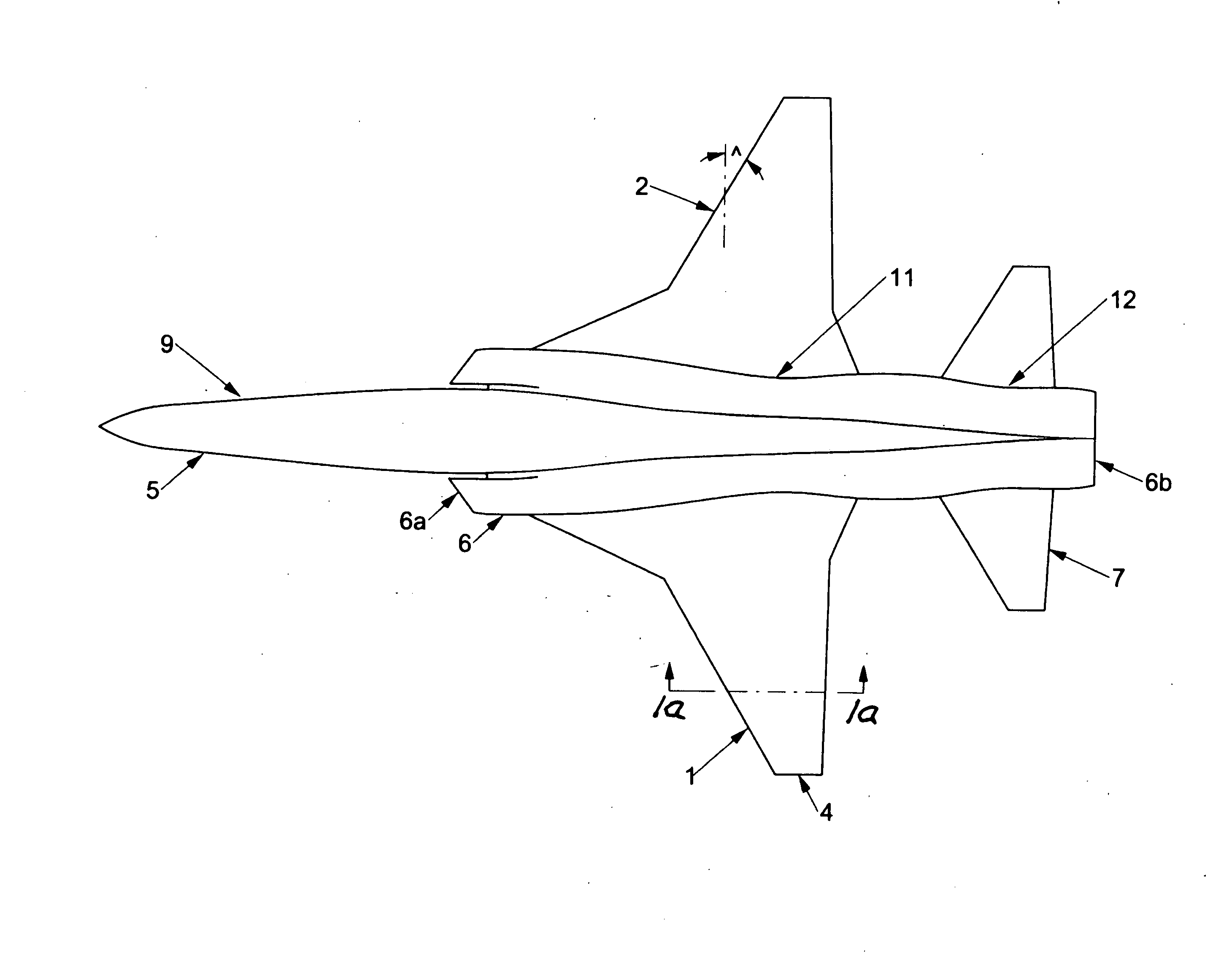
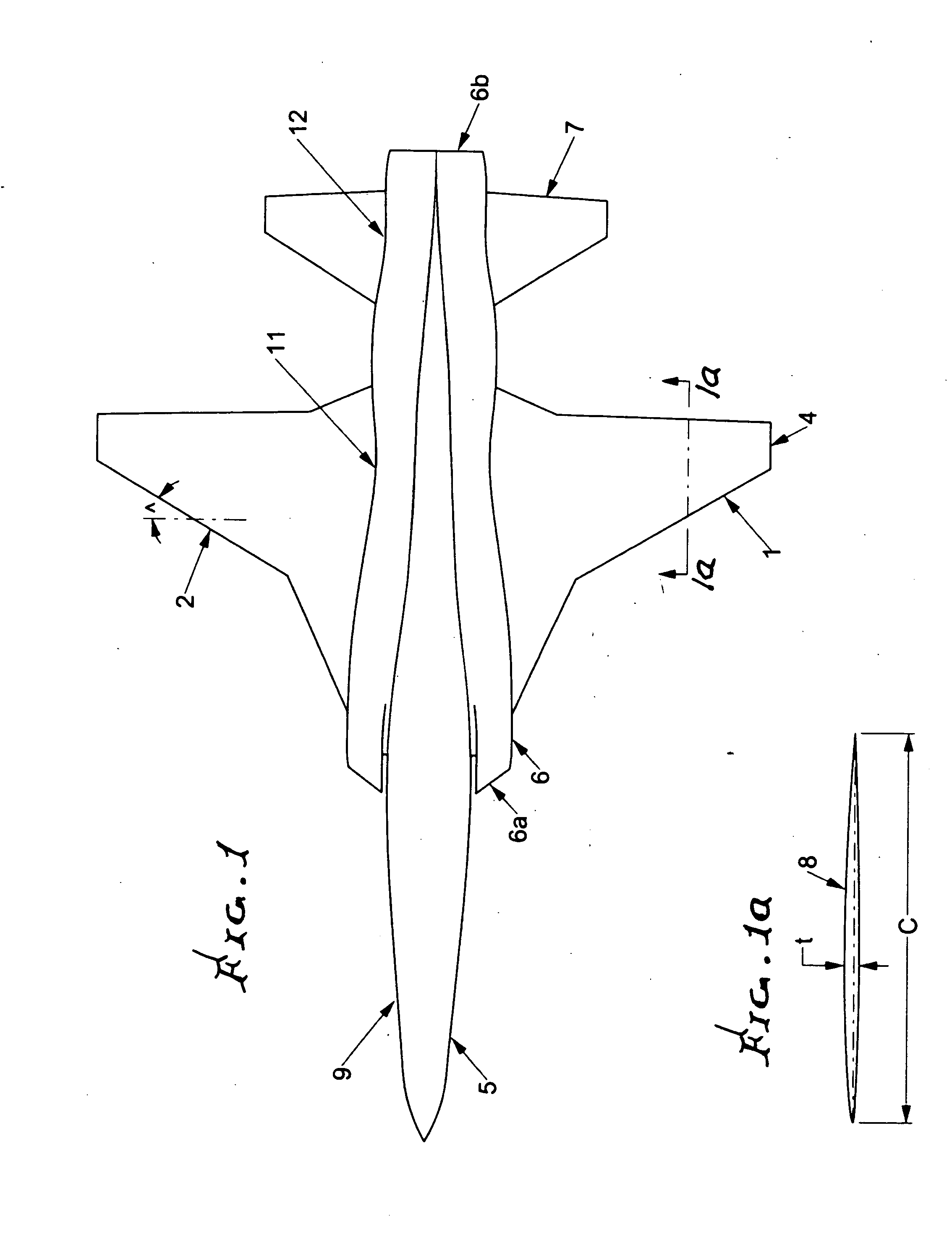
[0020]FIG. 1 shows an aircraft 9 incorporating the invention including a fuselage 5, a jet engine nacelle 6 including inlet and exhaust ends 6a and 6b, tail 7 and wing 1. An integrated fuselage / nacelle is illustrated, but the invention applies also to aircraft with separate engine nacelles mounted on the wing or fuselage.

[0021]The wing leading edge sweep angle ̂ is defined as the minimum angle of the outboard trapezoidal wing leading edge 2 relative to a line projected normally outboard from the aircraft longitudinal axis. FIG. 1a is a chordwise vertical section A-A through the wing 8, and is generally representative of the wing t / c ratio, where these dimensions are shown in section A-A. For the present purposes, the wing t / c is defined as the average of the t / c values along the wing span from a location outboard of the zone of appreciable fuselage influence on wing drag to the wing tip 4.

[0022]Location 11 shows a reduction in cross-sectional area of the fuselage and / or nacelle adja...


PUM


Abstract

On an aircraft designed for maximum efficient cruise speed in the range from about Mach 0.8 to about Mach 1.2, and having fuselage and wings with: (a) less than about 25 degrees of leading edge sweep, in combination with airfoil thickness to chord ratios between about 3% and about 8%, as an average along the wing semi-span outboard from the zone of substantial fuselage influence, and (b) wing leading edge sweep between about 20 degrees and about 35 degrees, in combination with airfoil thickness to chord ratios equal to or below about 3% as an average along the semi-span outboard from the zone of substantial fuselage influence to the wing tip.

Description

[0001]This invention relates generally to the configuration of transonic aircraft with wings designed for extensive natural laminar flow (NLF), and more particularly to optimization of wing thickness, sweep and fuselage cross section relationship criteria, for such transonic aircraft. This is a continuation in part of our prior application, LAMINAR FLOW WING OPTIMIZED FOR SUPERSONIC CRUISE AIRCRAFT Ser. No. 12 / 589,424, filed Oct. 26, 2009.BACKGROUND OF THE INVENTION[0002]Transonic NLF wing aircraft configurations as described herein are desirable for efficient transonic cruise, e.g. high subsonic speeds typically above about Mach 0.80 and up to slightly above Mach 1. Principal features of the herein described configurations are low to moderate sweep, sharp or slightly blunted leading edge, and relatively thin airfoils in terms of the ratio of maximum airfoil thickness to chord (t / c). The importance of the NLF boundary layer (BL) in terms of drag reduction can be understood by consid...

Claims


Application Information

Patent Timeline
IPC IPC(8): B64C3/14B64C30/00B64F5/00B64C3/16
CPCB64C3/10Y02T50/12B64C30/00B64C3/14Y02T50/10
Inventor TRACY, RICHARD R.CHASE, JAMES D.
Owner AERION INTPROP MANAGEMENT CORP
Why Eureka
Try Eureka