Network Driven L3 Control Signalling Prioritization

a network-driven, l3-controlled technology, applied in the field of telecommunications, can solve the problems of insufficient resource utilization, direct impact on the quality of service (qos) of user plane data transmission, network failure, etc., and achieve the effect of saving air interface resources

Active Publication Date: 2012-02-23
TELEFON AB LM ERICSSON (PUBL)
View PDF2 Cites 58 Cited by
  • Summary
  • Abstract
  • Description
  • Claims
  • Application Information

AI Technical Summary

Benefits of technology

[0030]Since both the type of signaling and the size of the corresponding message is predicted, the network can cancel the corresponding Buffer Status Report (BSR) and save air interface resources and L3 signaling delay.

Problems solved by technology

The performance of L3 control signaling, in terms of delay, directly impacts the quality of service (QoS) of the user plane data transmission.
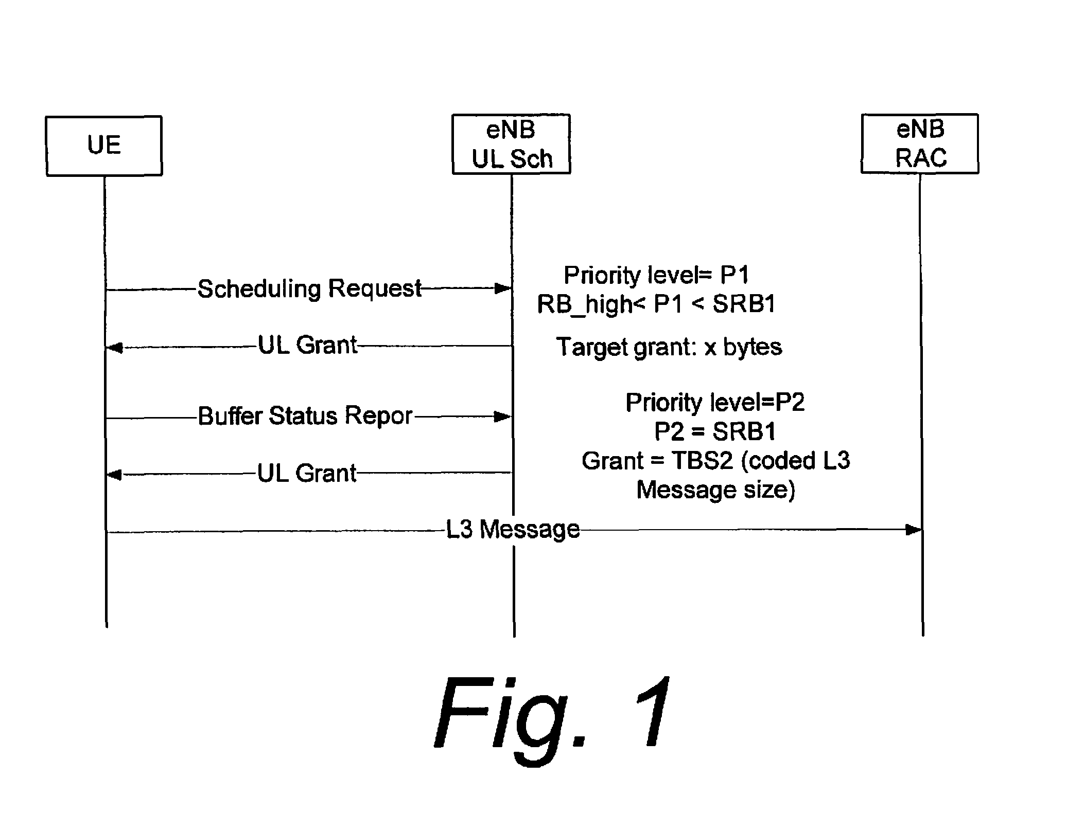
However, in uplink, the network does not have information about the types of transmissions the wireless terminals want to send to the network until it receives a Buffer Status Report (BSR) from the wireless terminals.
Several problems attend the existing approach of uplink prioritization.
For example, the current approach does not solve the problem that eNodeB has no knowledge about buffer of the wireless terminal before the eNodeB receives a Buffer Status Report (BSR), so the same priority level is set both for wireless terminals having the important L3 signaling and wireless terminals having normal data.
When resources are limited, the eNodeB may sacrifice or overlook the wireless terminal that actually has L3 signaling in its buffer.
Another problem with the current approach is that the buffer estimate x attributed to the buffer of a wireless terminal is assumed to be an arbitrary and fixed value.
An increased number of communications will result in insufficient resource usage, and possibly extra user plane delay.
Moreover, as understood from the above, the wireless terminal sending both a Scheduling Request (SR) and a Buffer Status Report (BSR) can waste resources over the air interface and add a large delay before the corresponding L3 signaling is actually sent.

Method used


Image

  • Network Driven L3 Control Signalling Prioritization
  • Network Driven L3 Control Signalling Prioritization
  • Network Driven L3 Control Signalling Prioritization

Examples


Embodiment Construction

[0040]In the following description, for purposes of explanation and not limitation, specific details are set forth such as particular architectures, interfaces, techniques, etc. in order to provide a thorough understanding of the present invention. However, it will be apparent to those skilled in the art that the present invention may be practiced in other embodiments that depart from these specific details. That is, those skilled in the art will be able to devise various arrangements which, although not explicitly described or shown herein, embody the principles of the invention and are included within its spirit and scope. In some instances, detailed descriptions of well-known devices, circuits, and methods are omitted so as not to obscure the description of the present invention with unnecessary detail. All statements herein reciting principles, aspects, and embodiments of the invention, as well as specific examples thereof, are intended to encompass both structural and functiona...


PUM


Abstract

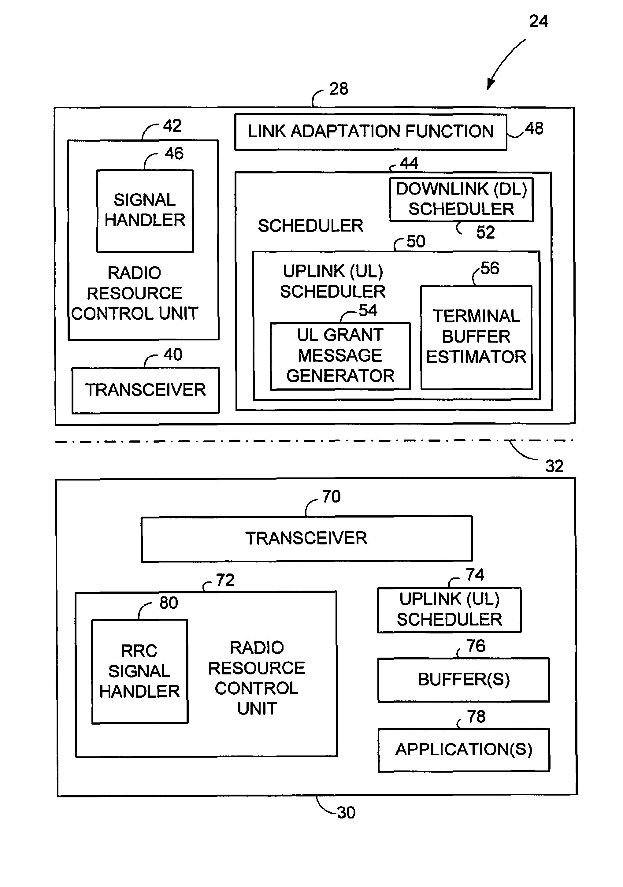
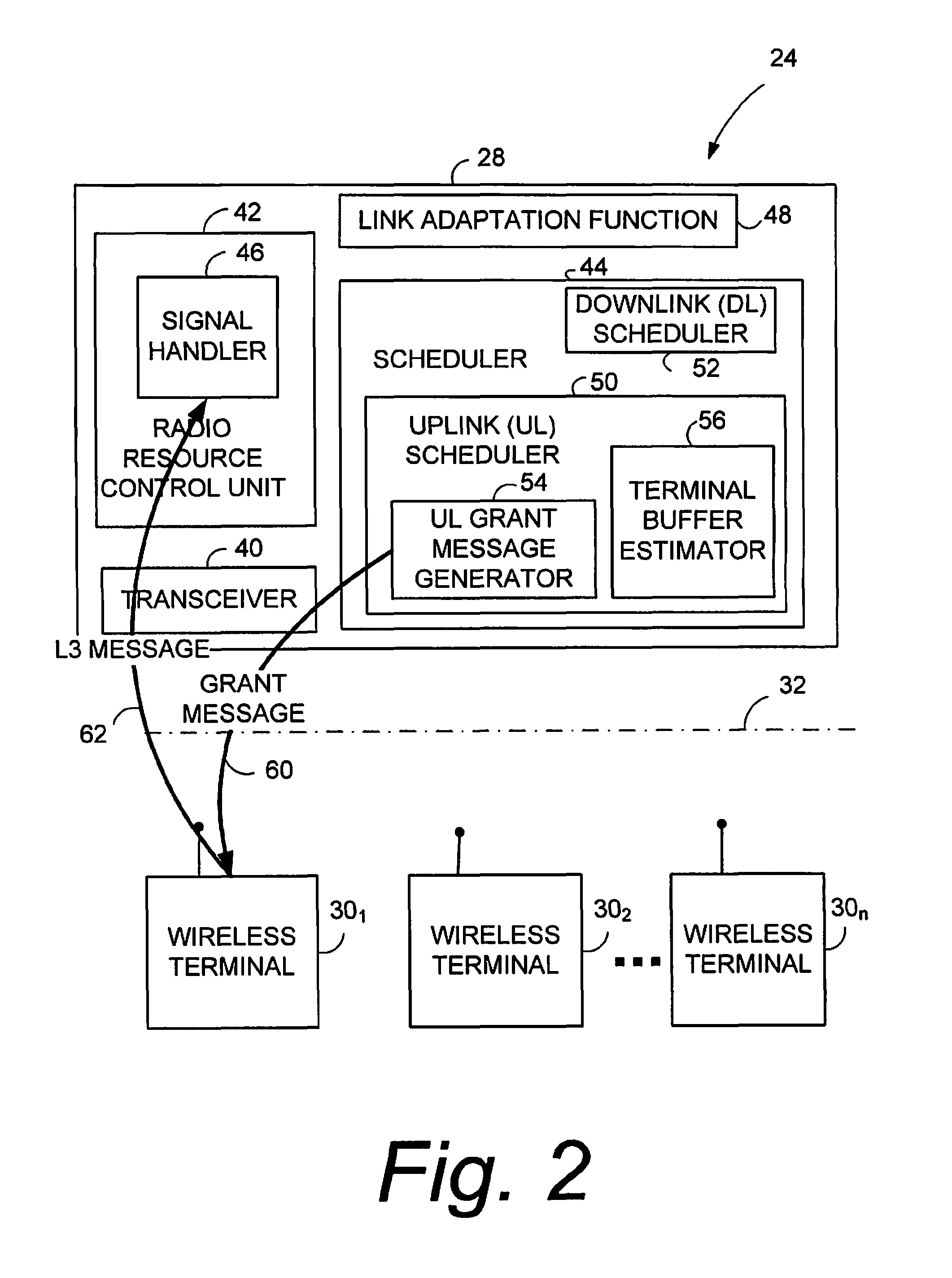
A node of a radio access network includes a transceiver and a radio resource control unit. The transceiver is configured to facilitate communication with plural wireless terminals over a radio interface including transmissions on an uplink from the wireless terminals to the node and transmissions on a downlink from the node to the wireless terminals.
The radio resource control unit configured to perform radio resource control functionality including layer three (L3) signaling between the node and the wireless terminals. The radio resource control unit includes an uplink scheduler configured to predict transmission of an uplink L3 message from the wireless terminals to the node and, for a particular wireless terminal, to generate, for transmission on the downlink, a grant message which in accordance with the prediction prioritizes a predicted L3 message of the particular wireless terminal relative to messages of others of the plural wireless terminals.

Description

BACKGROUND[0001]I. Technical Field[0002]This invention pertains to telecommunications, and particularly prioritization of communications on an uplink from plural wireless terminals to a radio access network node.[0003]II. Related Art and Other Considerations[0004]In a typical cellular radio system, wireless terminals (also known as mobile stations and / or user equipment units (UEs)) communicate via a radio access network (RAN) to one or more core networks. The wireless terminals can be mobile stations or user equipment units (UE) such as mobile telephones (“cellular” telephones) and laptops with wireless capability), e.g., mobile termination), and thus can be, for example, portable, pocket, hand-held, computer-included, or car-mounted mobile devices which communicate voice and / or data with radio access network.[0005]The radio access network (RAN) covers a geographical area which is divided into cell areas, with each cell area being served by a base station, e.g., a radio base station...

Claims


Application Information

Patent Timeline
Patent Type & Authority Applications(United States)
IPC IPC(8): H04W74/04H04W72/23H04W72/566
CPCH04W72/1242H04W72/1289H04W72/569H04W72/23
Inventor SUN, YINGSKARBY, CHRISTIANPETERS, GUNNARMALITI, KELVINNORLUND, KRISTER
Owner TELEFON AB LM ERICSSON (PUBL)
Why Eureka
Try Eureka