
Sound source separation apparatus and sound source separation method

a separation matrix and sound source technology, applied in the field of sound source separation apparatus and sound source separation method, can solve the problems of not being able to separate sound source signal from input signal using separation matrix, noticeably changing the separation matrix, etc., to reduce the degree to which components, and reduce the effect of separation error

Active Publication Date: 2012-02-23
HONDA MOTOR CO LTD
View PDF2 Cites 22 Cited by
  • Summary
  • Abstract
  • Description
  • Claims
  • Application Information

AI Technical Summary

Benefits of technology

[0011]The invention is made in consideration of the above-mentioned problem and provides a sound source separation apparatus and a sound source separation method which can separate a sound source signal even when a sound source changes.
[0023]In the sound source separation apparatus according to the fifth aspect of the invention, it is possible to reduce the degree to which components based on different sound sources are mixed as a single sound source or a separation error.
[0024]In the sound source separation apparatus according to the sixth aspect of the invention, it is possible to reduce the degree to which components based on different sound sources are mixed as a single sound source and to reduce separation error.

Problems solved by technology

However, in the sound source separation system described in Japanese Patent No. 4444345, when a sound source changes, the separation matrix noticeably changes.
Therefore, there is a problem in that a sound source signal cannot be separated from the input signals using the separation matrix.

Method used


Image

  • Sound source separation apparatus and sound source separation method
  • Sound source separation apparatus and sound source separation method
  • Sound source separation apparatus and sound source separation method

Examples


Embodiment Construction

[0033]Hereinafter, an embodiment of the invention will be described with reference to the accompanying drawings.

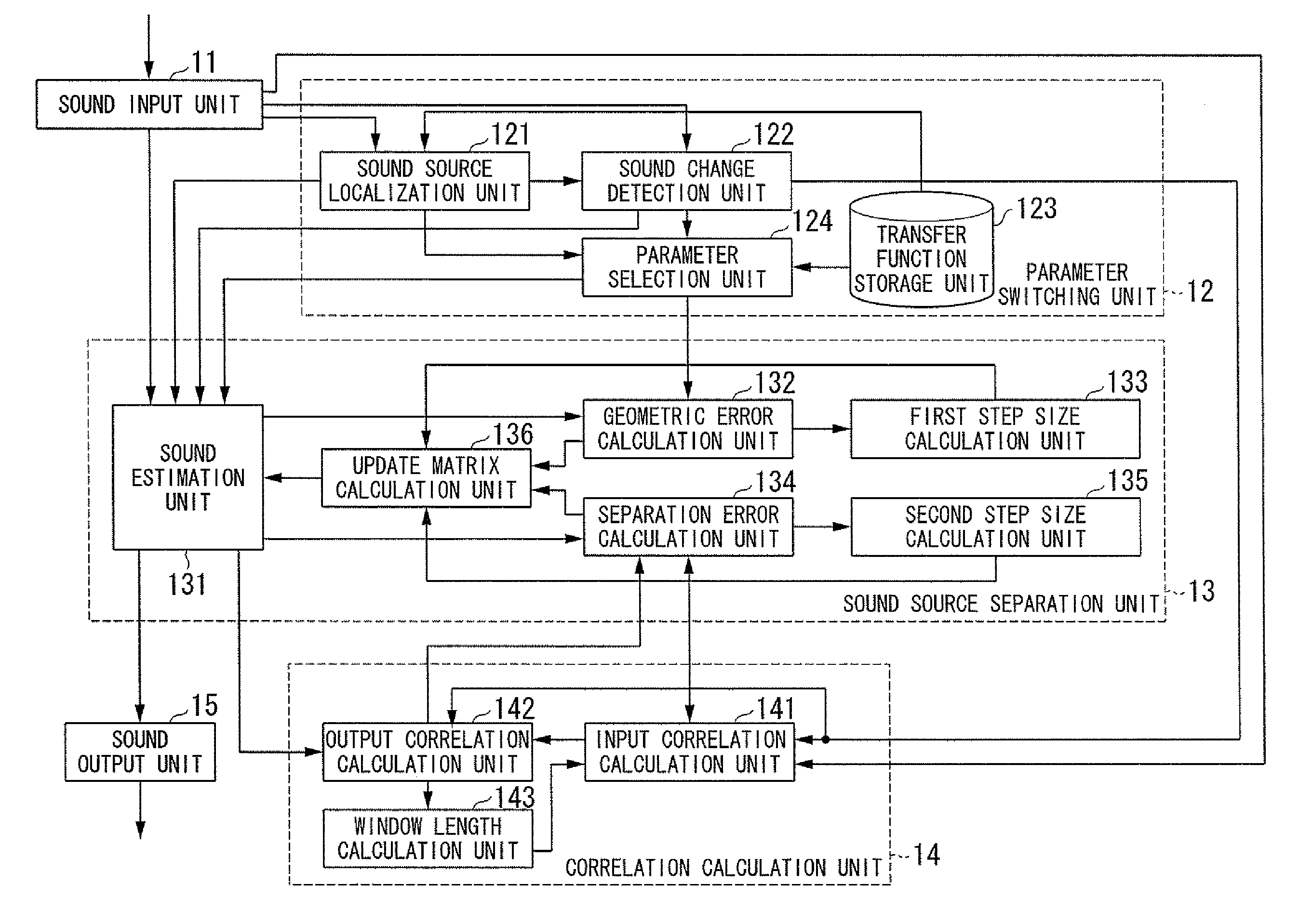
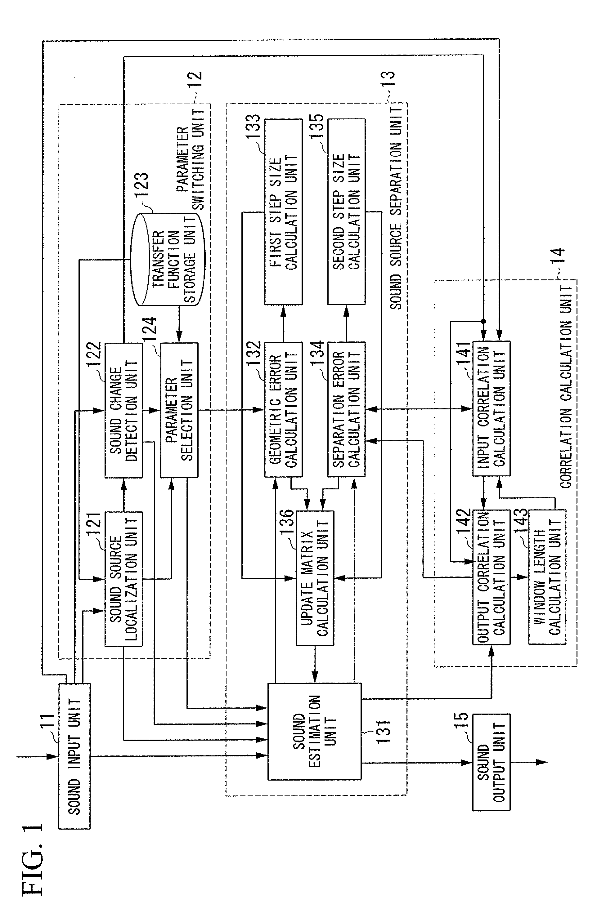
[0034]FIG. 1 is a diagram schematically illustrating the configuration of a sound source separation apparatus 1 according to an embodiment of the invention.

[0035]The sound source separation apparatus 1 includes a sound input unit 11, a parameter switching unit 12, a sound source separation unit 13, a correlation calculation unit 14, and a sound output unit 15.

[0036]The sound input unit 11 includes plural sound input elements (for example, microphones) that convert received sound waves into sound signals. The sound input elements are disposed at different positions. The sound input unit 11 is a microphone array including M (where M is an integer of 2 or greater) microphones.

[0037]The sound input unit 11 arranges and outputs the converted sound signals as a multichannel (for example, M-channel) sound signal to a sound source localization unit 121 and a sound change detection...


PUM


Abstract

A sound source separation apparatus includes a transfer function storage unit that stores a transfer function from a sound source, a sound change detection unit that generates change state information indicating a change of the sound source on the basis of an input signal input from a sound input unit, a parameter selection unit that calculates an initial separation matrix on the basis of the change state information generated by the sound change detection unit, and a sound source separation unit that separates the sound source from the input signal input from the sound input unit using the initial separation matrix calculated by the parameter selection unit.

Description

CROSS REFERENCE TO RELATED APPLICATIONS[0001]This application claims benefit from U.S. Provisional application Ser. No. 61 / 374,382, filed Aug. 17, 2010, the contents of which are incorporated herein by reference.BACKGROUND OF THE INVENTION[0002]1. Field of the Invention[0003]The present invention relates to a sound source separation apparatus and a sound source separation method.[0004]2. Description of Related Art[0005]A blind source separation (BSS) technique of separating signals from observed signals in which plural unknown signal sequences are mixed has been proposed. The BSS technique is applied, for example, to sound recognition under noisy conditions. The BSS technique is used to separate sound uttered by a person from ambient noise, the driving sound made by a robot's movement, and the like.[0006]In the BSS technique, spatial propagation characteristics from sound sources are used to separate signals.[0007]For example, a sound source separation system described in Japanese P...

Claims


Application Information

Patent Timeline
IPC IPC(8): H04R5/00G10L21/028G10L21/0308G10L25/51G10L25/78
CPCG10L21/028G10L2021/02166
Inventor NAKADAI, KAZUHIRONAKAJIMA, HIROFUMI
Owner HONDA MOTOR CO LTD
Learn More