User interface for segmented neurostimulation leads

Active Publication Date: 2012-02-23
BOSTON SCI NEUROMODULATION CORP
View PDF2 Cites 142 Cited by
  • Summary
  • Abstract
  • Description
  • Claims
  • Application Information

AI Technical Summary

Benefits of technology

[0015]In one embodiment, the electrodes are arranged axially along one or more neurostimulation leads, in which case, the first set of stimulation parameters may be designed to displace the electrical stimulation field along the neurostimulation lead(s), and the second set of stimulation parameters may be designed to expand or contract the electrical stimulation field along the neurostimulation lead(s). In another embodiment, the electrodes are arranged circumferentially about the one or more neurostimulation leads, in which case, the first set of stimulation parameters may be designed to displace the electrical stimulation field about the neurostimulation lead(s), and the second set of stimulation parameters may be designed to expand or contract the electrical stimulation field about the neurostimulation lead(s).
[0016]In accordance with a second aspect of the present inventions, the user interface includes a circumferential modification control element configured for being actuated (e.g., a rotational control element configured for being rotated about a point), and the processor is configured for generating a set of stimulation parameters designed to circumferentially displace a locus of the electrical stimulation field about the neurostimulation lead(s) when the rotational control element is rotated about the point.
[0017]In an optional embodiment, the user interface includes a marker associated with the rotational control element. The marker indicates the circumferential position of the locus of the electrical stimulation field. In another optional embodiment, the user interface includes a radial modification control element, and the processor is further configured for generating another set of stimulation parameters designed to radially displace the locus of the electrical stimulation field when the radial modification control element is actuated. The radial modification control element may be located on the rotational control element, in which case the radial modification control element may be configured for being radially displaced toward and away from the point of the rotational control element.
[0018]In accordance with a third aspect of the present invention, the user interface includes a circumferential modification control element configured for being continually (e.g., continuously or repeatedly) actuated, and the processor is configured for generating sets of stimulation parameters designed to circumferentially displace a locus of the electrical stimulation field about the neurostimulation lead(s) in a first rotational direction at respective different angular positions as the circumferential modification control element is continually actuated. The user interface may further include another circumferential modification control element configured for being continually actuated, in which case, the processor may be configured for generating other sets of stimulation parameters designed to circumferentially displace the locus of the electrical stimulation field about the

Problems solved by technology

Significantly, non-optimal electrode placement and stimulation parameter selections may result in excessive energy consumption due to stimulation that is set at too high an amplitude, too wide a pulse duration, or too fast a frequency; inadequate or marginalized treatment due to stimulation that is set at too low an amplitude, too narrow a pulse duration, or too slow a frequency; or stimulation of neighboring cell populations that may result in undesirable side effects.
Even with the electrodes are located predominately within the sensorimotor territory, the electrical field generated by DBS is non-discriminately applied to all neural elements surrounding the electro

Method used


Image

  • User interface for segmented neurostimulation leads
  • User interface for segmented neurostimulation leads
  • User interface for segmented neurostimulation leads

Examples


Embodiment Construction

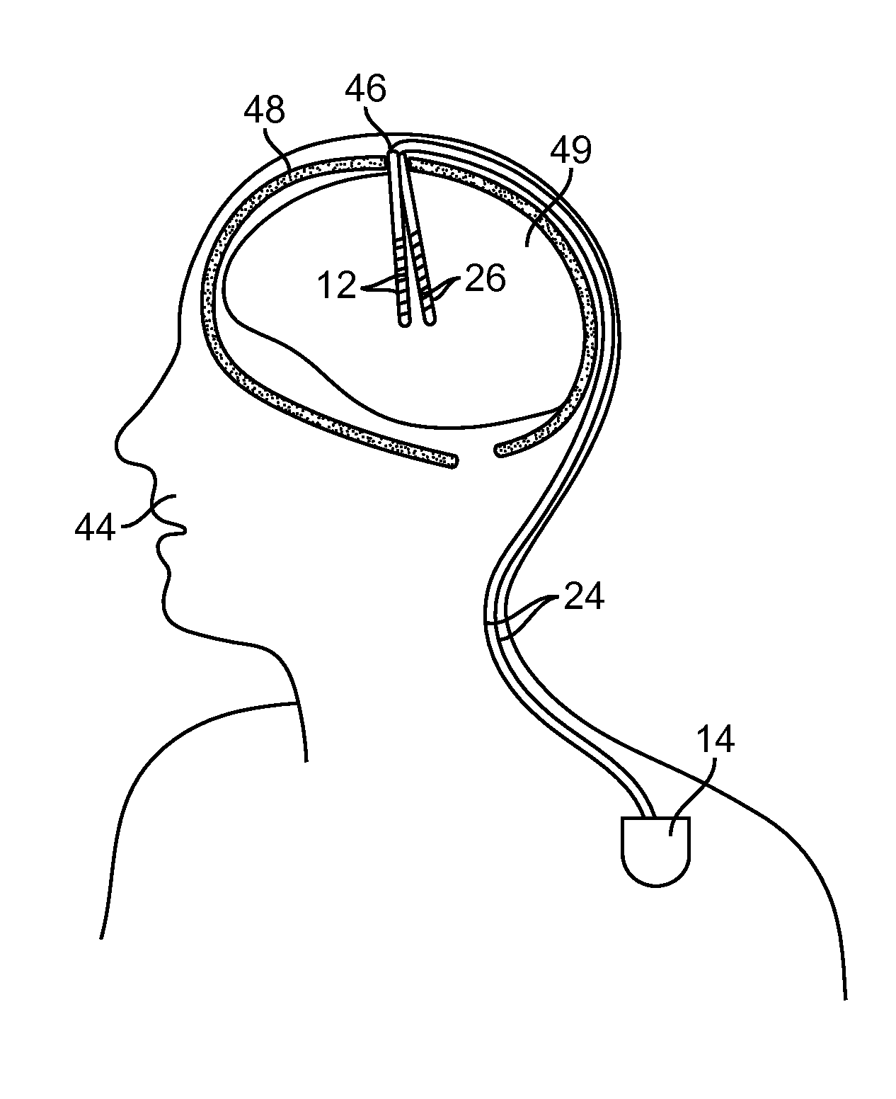
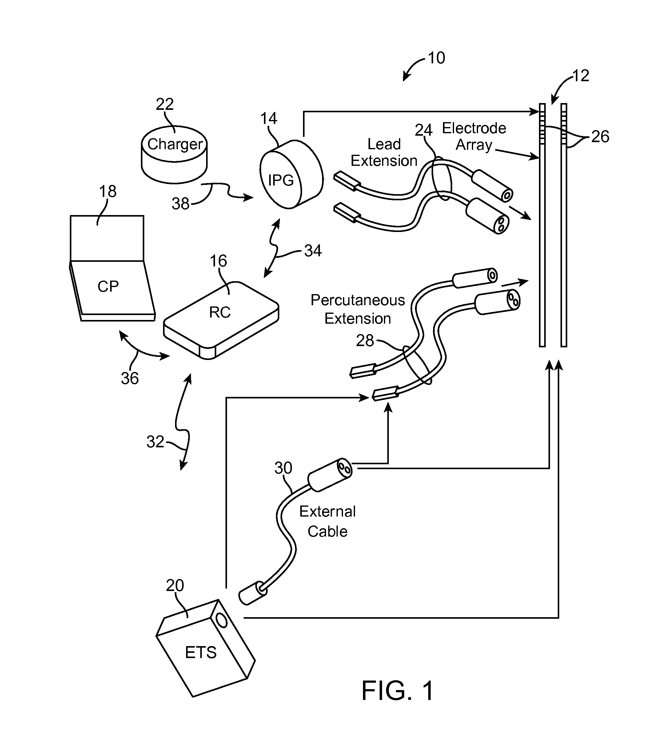
[0037]At the outset, it is noted that the present invention may be used with an implantable pulse generator (IPG), radio frequency (RF) transmitter, or similar neurostimulator, that may be used as a component of numerous different types of stimulation systems. The description that follows relates to a deep brain stimulation (DBS) system. However, it is to be understood that the while the invention lends itself well to applications in DBS, the invention, in its broadest aspects, may not be so limited. Rather, the invention may be used with any type of implantable electrical circuitry used to stimulate tissue. For example, the present invention may be used as part of a pacemaker, a defibrillator, a cochlear stimulator, a retinal stimulator, a stimulator configured to produce coordinated limb movement, a cortical stimulator, a spinal cord stimulator, peripheral nerve stimulator, microstimulator, or in any other neural stimulator configured to treat urinary incontinence, sleep apnea, sh...


PUM


Abstract

An external control device for use with a neurostimulation system having a plurality of electrodes capable of conveying an electrical stimulation field into tissue in which the electrodes are implanted is provided. The external control device comprises a user interface having one or more control elements, a processor configured for generating stimulation parameters designed to modify the electrical stimulation field relative to one or more neurostimulation lead carrying the electrodes. The external control device further comprises output circuitry configured for transmitting the stimulation parameters to the neurostimulation system.

Description

RELATED APPLICATION DATA[0001]The present application claims the benefit under 35 U.S.C. §119 to U.S. provisional patent application Ser. No. 61 / 374,879, filed Aug. 18, 2010. The foregoing application is hereby incorporated by reference into the present application in its entirety.FIELD OF THE INVENTION[0002]The present invention relates to tissue stimulation systems, and more particularly, to user interfaces and methods for controlling the distribution of electrical current on segmented neurostimulation leads.BACKGROUND OF THE INVENTION[0003]Implantable neurostimulation systems have proven therapeutic in a wide variety of diseases and disorders. Pacemakers and Implantable Cardiac Defibrillators (ICDs) have proven highly effective in the treatment of a number of cardiac conditions (e.g., arrhythmias). Spinal Cord Stimulation (SCS) systems have long been accepted as a therapeutic modality for the treatment of chronic pain syndromes, and the application of tissue stimulation has begun...

Claims


Application Information

Patent Timeline
IPC IPC(8): A61N1/08
CPCA61N1/36064A61N1/36067A61N1/36071A61N1/36182G06F19/3406A61N1/0534A61N1/36082A61N1/37247G16H40/63A61N1/36185
Inventor MOFFITT, MICHAEL A.KOTHANDARAMAN, SRIDHARMAKOUS, JAMES C.
Owner BOSTON SCI NEUROMODULATION CORP
Why Eureka
Try Eureka