
Egr mixer

a technology of egr mixer and egr mixer, which is applied in the direction of mechanical equipment, machines/engines, and non-fuel substance addition to fuel, etc. it can solve the problems of insufficient exhaust gas supply, insufficient wide opening of conventional egr mixer, and ineffective restriction of fresh air flow. , to achieve the effect of increasing vacuum, increasing velocity, and effective restricting fresh air flow

Inactive Publication Date: 2012-03-01
DENSO CORP
View PDF0 Cites 14 Cited by
  • Summary
  • Abstract
  • Description
  • Claims
  • Application Information

AI Technical Summary

Benefits of technology

[0006]It is an object of the present invention to provide an EGR mixer which can overcome the above mentioned problem. It is another object of the present invention to provide an EGR mixer being capable of suppressing pressure loss and increasing an amount of exhaust gas.

Problems solved by technology

Therefore, attempt to improve sucking performance may adversely increase pressure loss in the fresh air flow.
In another aspect, conventional designs of the EGR mixers could not obtain a sufficiently wide opening on a sucking opening for exhaust gas to a vacuum region created by the fresh air flow.
Therefore, conventional EGR mixers could not supply sufficient amount of exhaust gas.

Method used


Image

  • Egr mixer
  • Egr mixer
  • Egr mixer

Examples


first embodiment

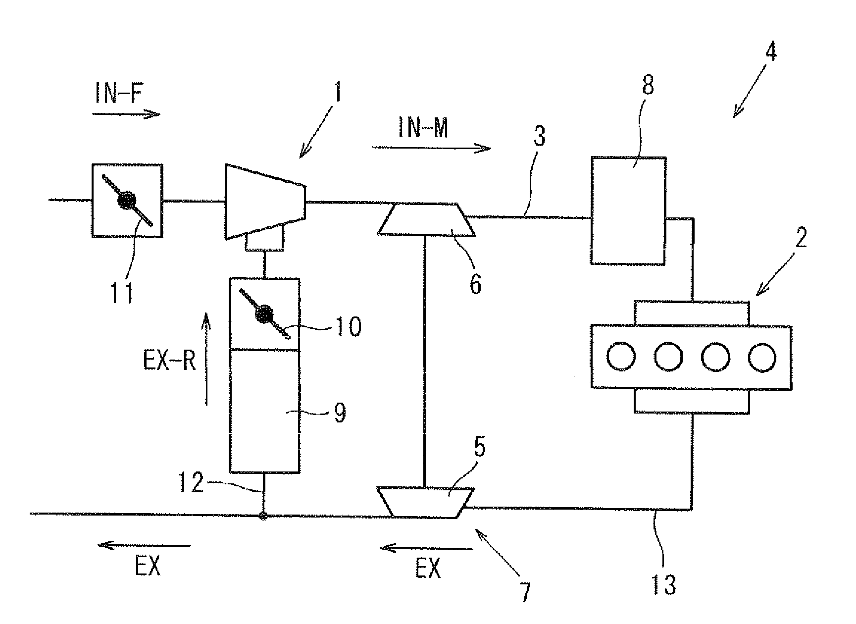
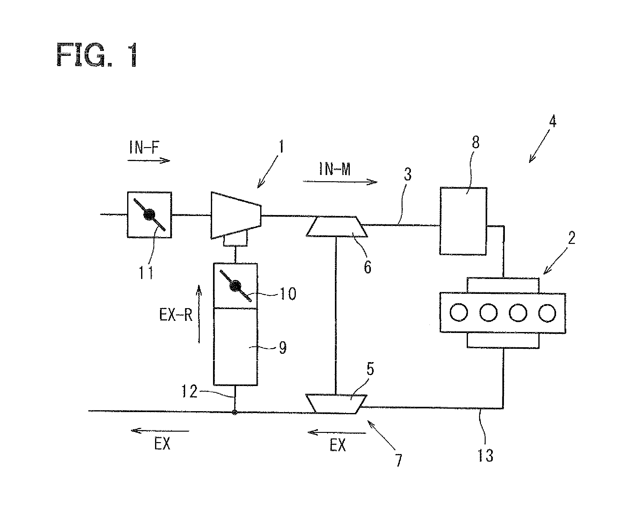
[0040]FIG. 1 is a block diagram of an intake and exhaust system for an internal combustion engine (engine) 2. The system includes an exhaust gas recirculation (EGR) system which includes an EGR mixer 1 according to a first embodiment of the invention. The EGR mixer 1 is a component of an intake and exhaust system 4 for the engine 2. The EGR mixer 1 is installed in an intake passage 3 of the engine 2. The EGR mixer 1 contributes to perform an exhaust gas recirculation (EGR) process in which a part of exhaust gas (EX) exhausted from the engine 2 is returned to the intake passage 3 and is sucked into the engine 2. The EGR mixer 1 creates mixture (IN-M) by mixing returned exhaust gas (EX-R) into fresh air (IN-F).

[0041]The intake and exhaust system 4 includes a plurality of components, such as a turbo charger 7, an inter cooler 8, an EGR cooler 9, an EGR valve 10, and a throttle valve 11. The turbo charger 7 has a turbine 5 and a compressor 6. The turbo charger 7 compresses a mixture gas...


PUM


Abstract

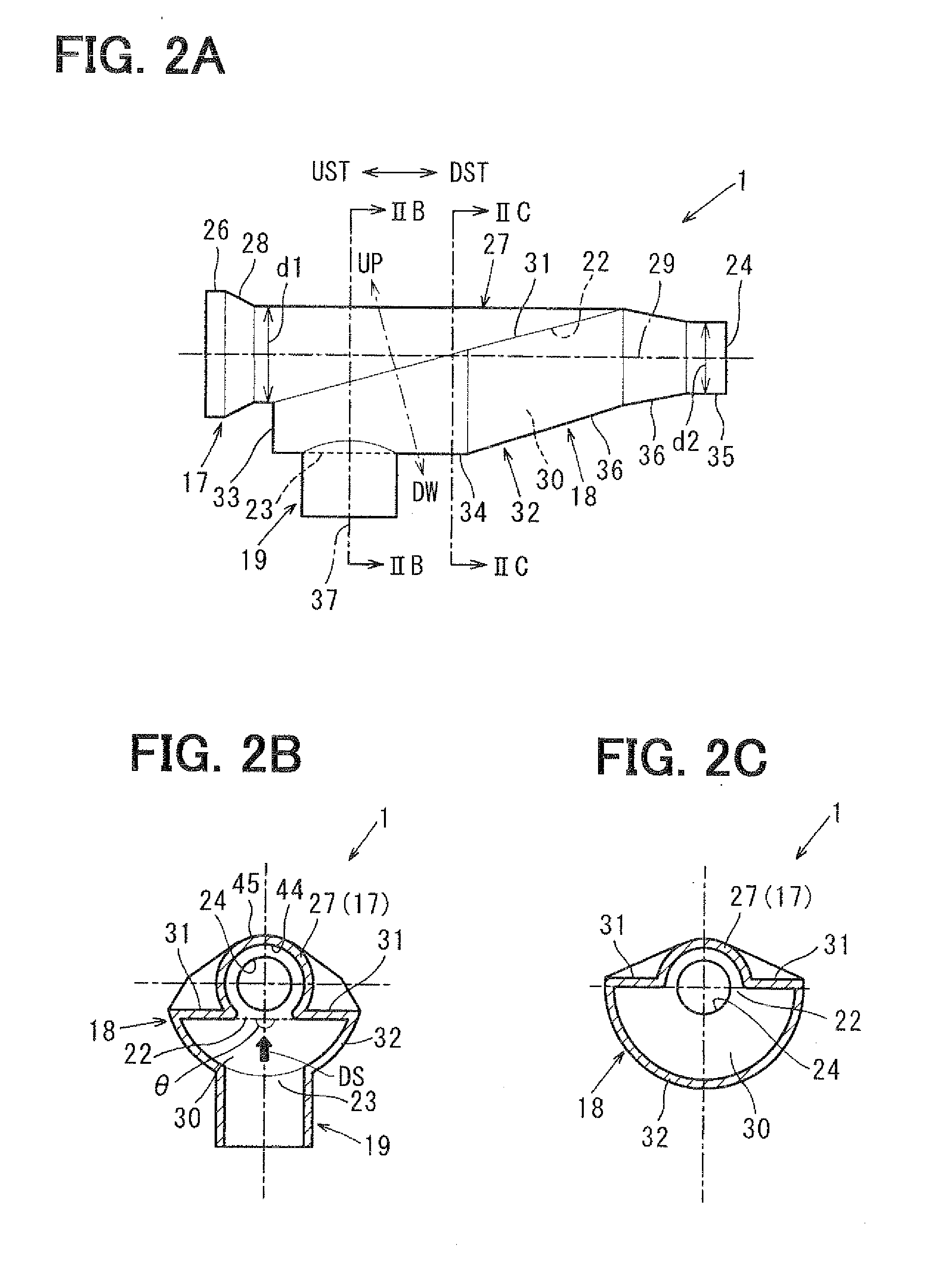
An EGR mixer has a mixing shell which defines a mixing cavity only on the down side, and does not define the mixing cavity on the up side. The EGR mixer has a primary internal opening for fresh air, which is formed so that an opening plane is inclined to a side so that the opening plane faces a secondary internal opening for exhaust gas. The primary internal opening and the secondary internal opening are arranged to allow exhaust gas to enter into the primary internal opening. The exhaust gas restricts a fresh air flow so that the fresh air flow creates increased vacuum. It is possible to suppress pressure loss and to increase an amount of exhaust gas.

Description

CROSS REFERENCE TO RELATED APPLICATION[0001]This application is based on Japanese Patent Application No. 2010-189668 filed on Aug. 26, 2010, the contents of which are incorporated herein by reference in its entirety.FIELD OF THE INVENTION[0002]The present disclosure relates to an apparatus, an EGR mixer, for mixing fresh air and exhaust gas in an exhaust gas recirculation (EGR) system.BACKGROUND OF THE INVENTION[0003]Conventionally, an exhaust gas recirculation system (EGR) is known in this field. The EGR system returns a part of exhaust gas exhausted from the internal combustion engine to an intake line, and makes the internal combustion engine inhales the exhaust gas. To perform exhaust gas recirculation process, it is known to employ an EGR mixer, which creates mixture of fresh air and exhaust gas by mixing a part of the exhaust gas into fresh air.[0004]JP-A-2007-092592 discloses an EGR mixer which mixes fresh air and exhaust gas by generating the Venturi effect on a fresh air fl...

Claims


Application Information

Patent Timeline
IPC IPC(8): F02M25/07
CPCF02M25/0709Y02T10/121F02M25/0731F02M25/0722F02M26/06F02M26/19F02M26/28
Inventor TAKAGI, HIROYUKIHAYASHI, TOSHIONISHIO, YOSHITAKA
Owner DENSO CORP
Learn More