Heat pipe with composite wick structure

a technology of heat pipes and wicks, applied in indirect heat exchangers, lighting and heating apparatus, etc., can solve the problems of insufficient and achieve the effect of improving the efficiency of work fluid backflow

Inactive Publication Date: 2012-03-01
KUNSHAN JUZHONG ELECTRONICS
View PDF11 Cites 19 Cited by
  • Summary
  • Abstract
  • Description
  • Claims
  • Application Information

AI Technical Summary

Benefits of technology

[0006]An object of the invention is to improve the efficiency of f

Problems solved by technology

The efficiency of flowing back of

Method used


Image

  • Heat pipe with composite wick structure
  • Heat pipe with composite wick structure
  • Heat pipe with composite wick structure

Examples


Embodiment Construction

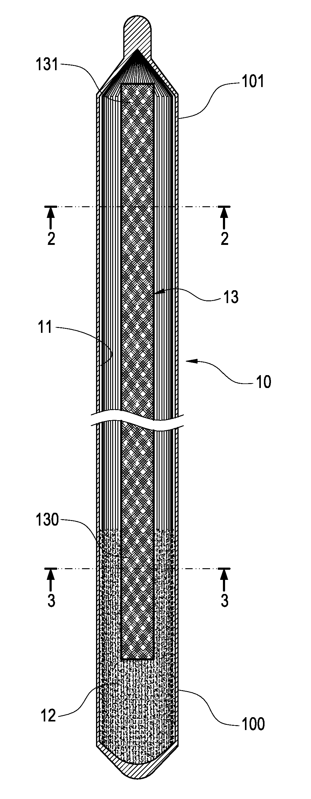
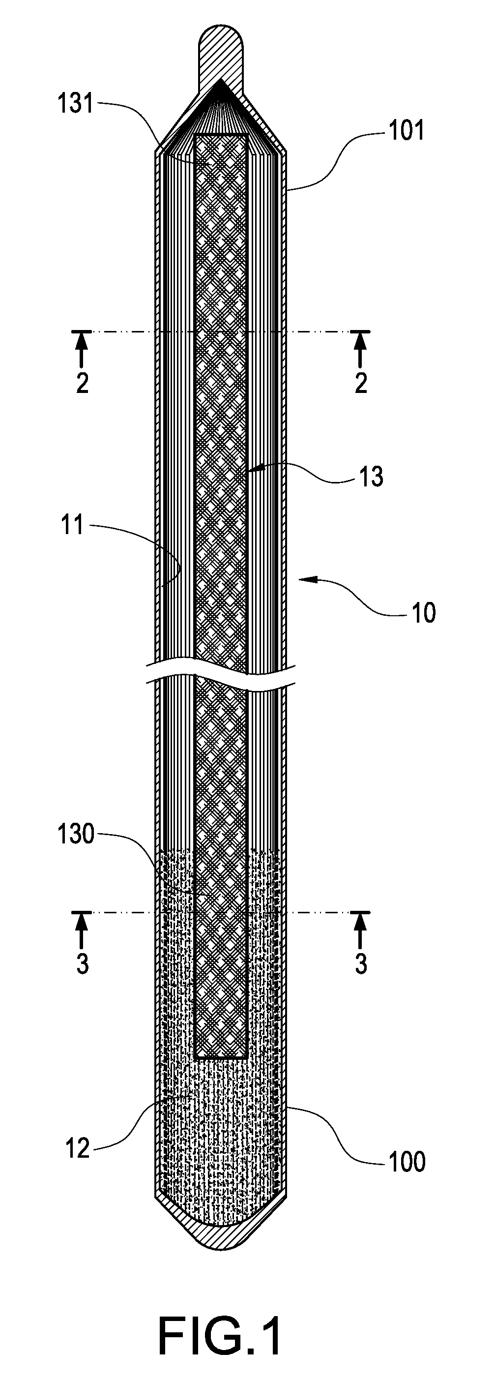
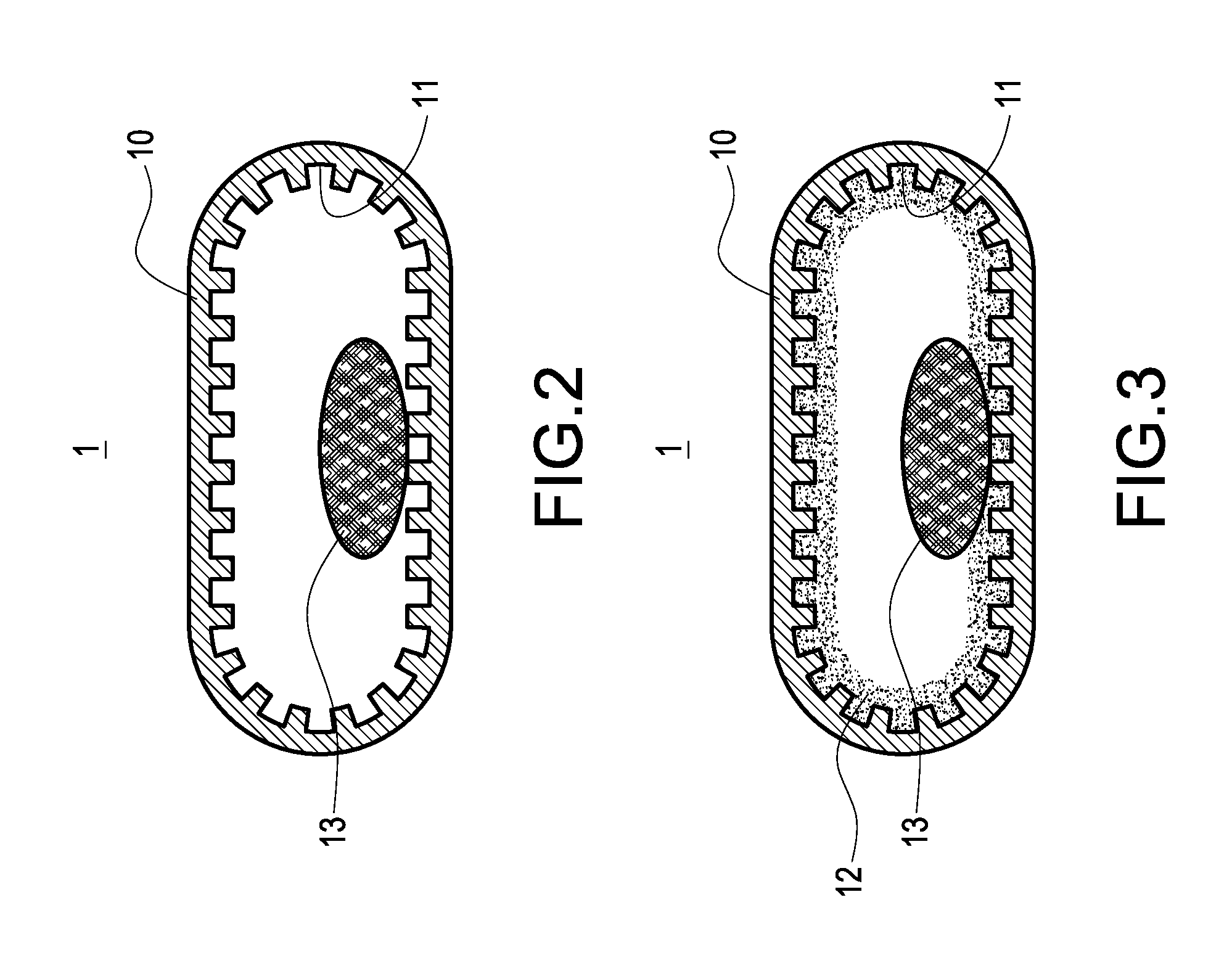
[0015]Please refer to FIGS. 1 and 4. The heat pipe of the invention includes a tube 10, a grooved wick 11, a porous wick 12 and a fiber wick 13.

[0016]An evaporating portion 100 and a condensing portion 101 are defined in the tube 10. In the shown embodiment, the evaporating portion 100 and the condensing portion 101 are separately located at two ends of the tube 10. Of course, there may be a plurality of evaporating portions 100 or condensing portions 101. The grooved wick 11 is longitudinally and entirely disposed on an inner wall of the tube 10 and communicates the evaporating portion 100 and the condensing portion 101. A work fluid (not shown) contained in the tube 10 may flow back from the condensing portion 101 to the evaporating portion 100 through the grooved wick 11.

[0017]The porous wick 12 is made of sintered powder. The porous wick 12 is only disposed on the inner wall of the evaporating portion 100 and covers the grooved wick 11 in the evaporating portion 100.

[0018]Please...


PUM


Abstract

The heat pipe of the invention includes a tube in which an evaporating portion and a condensing portion are defined; a grooved wick longitudinally and entirely disposed on an inner wall of the tube and communicating the evaporating portion with the condensing portion; a porous wick only disposed on the inner wall of the evaporating portion and covering the grooved wick in the evaporating portion; and a fiber wick in a shape of a strip, whose one end connects the porous wick and whose the other end longitudinally extends to the condensing portion.

Description

BACKGROUND OF THE INVENTION[0001]1. Technical Field[0002]The invention generally relates to heat transfer elements, particularly to heat pipes.[0003]2. Related Art[0004]A heat pipe is a heat transfer element which employing phase transition to efficiently transfer heat between two solid interfaces. Usually, an evaporating portion and a condensing portion are separately defined at two ends of a heat pipe. At the evaporating portion, a work fluid within the heat pipe turns into a vapor by absorbing the heat. The vapor condenses back into a liquid at the condensing portion, releasing the latent heat by a heat sink. The liquid then returns to the evaporating portion through either capillary action or gravity action where it evaporates once more and repeats the cycle.[0005]In practice, heat pipes are not always arranged in a direction that the evaporating portion is downward. Sometimes a heat pipe may be arranged reversely or obliquely. This tends to make the work fluid which is in liqui...

Claims


Application Information

Patent Timeline
IPC IPC(8): F28D15/04
CPCF28D15/046F28D15/0233
Inventor HUANG, YU- POKUO, TUNG-JUNG
Owner KUNSHAN JUZHONG ELECTRONICS
Why Eureka
Try Eureka