Ceramic heat exchanger and method of producing same

a ceramic heat exchanger and ceramic heat exchanger technology, applied in indirect heat exchangers, metal-working equipment, lighting and heating equipment, etc., can solve the problems of difficult to work with materials into complicated shapes and high costs, and achieve the effects of reducing joints, less likely to leakage, and easy production

Inactive Publication Date: 2012-03-01
IHI CORP +1
View PDF10 Cites 10 Cited by
  • Summary
  • Abstract
  • Description
  • Claims
  • Application Information

AI Technical Summary

Benefits of technology

[0016]In the ceramic heat exchanger and the method of producing same according to the present invention, the ceramic heat exchanger is composed of a body and lids, and produced by joining only the body and the lids. Such ceramic heat exchanger has reduced joints, and thus, is easy to produce and less likely to leak.

Problems solved by technology

Commonly used in high-temperature applications are metallic plate-fin heat exchangers, which exhibit high effectiveness, but have a drawback that complicated fin shapes lead to high costs.
Ceramic is, however, a material difficult to work into complicated shapes because of its high hardness and brittleness.

Method used


Image

  • Ceramic heat exchanger and method of producing same
  • Ceramic heat exchanger and method of producing same
  • Ceramic heat exchanger and method of producing same

Examples


Embodiment Construction

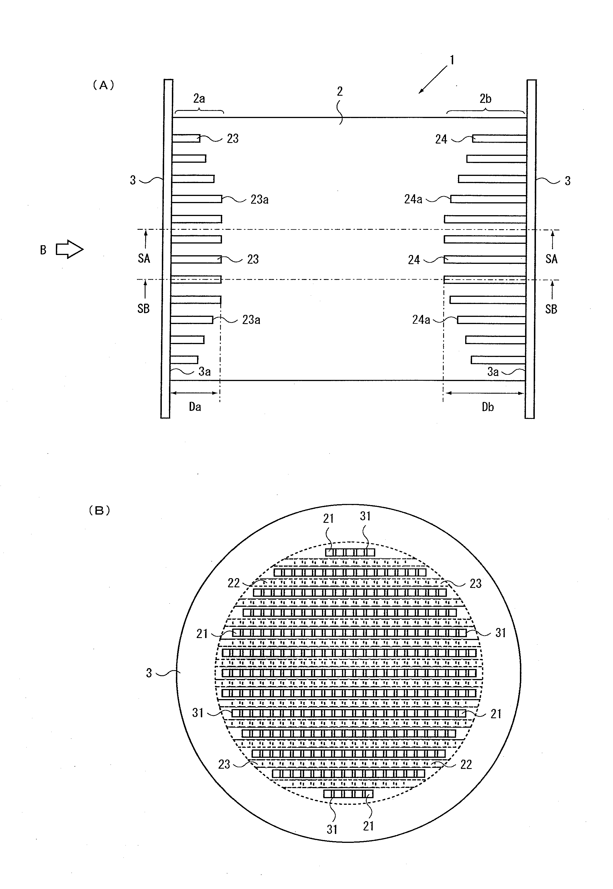
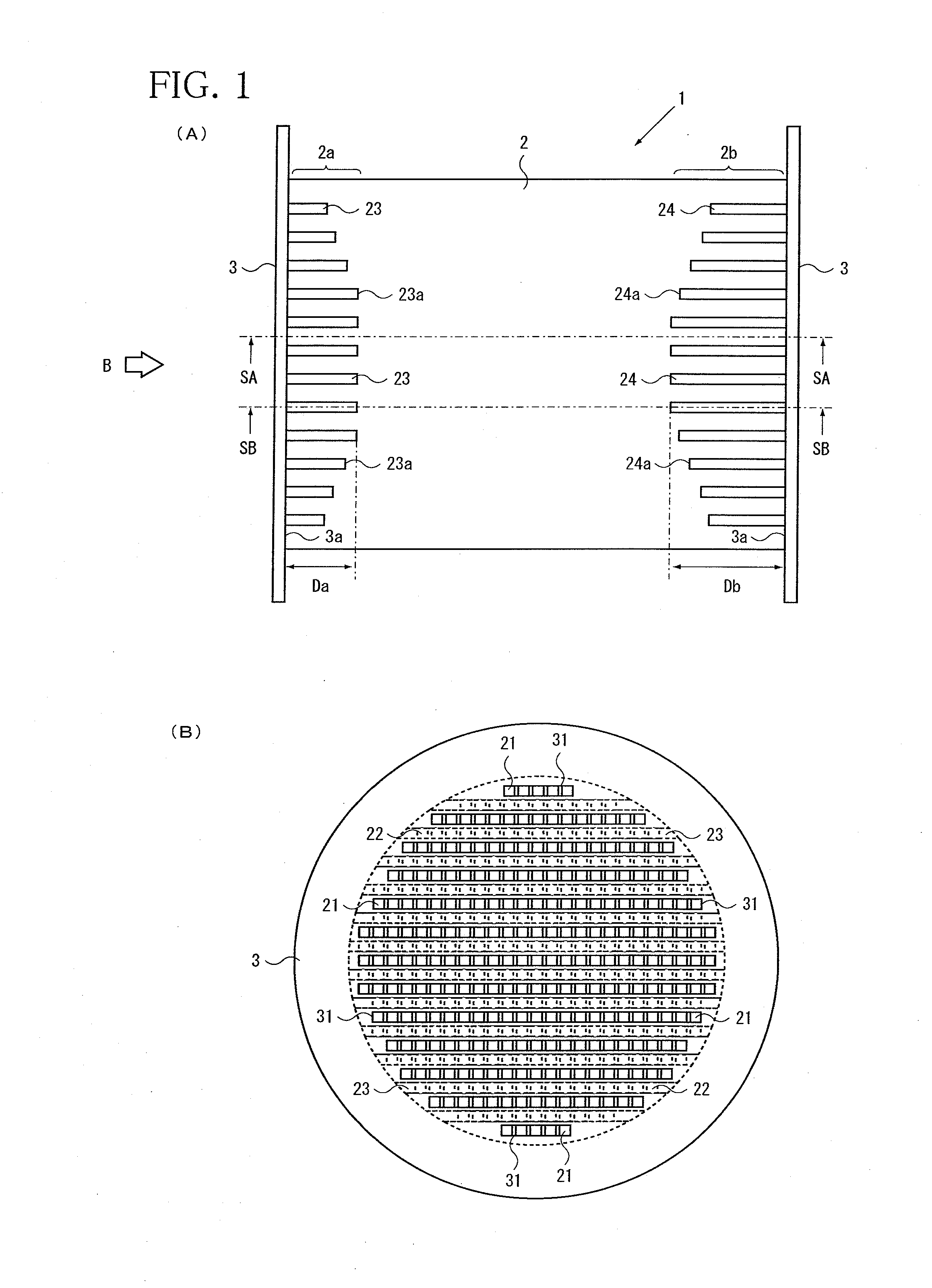
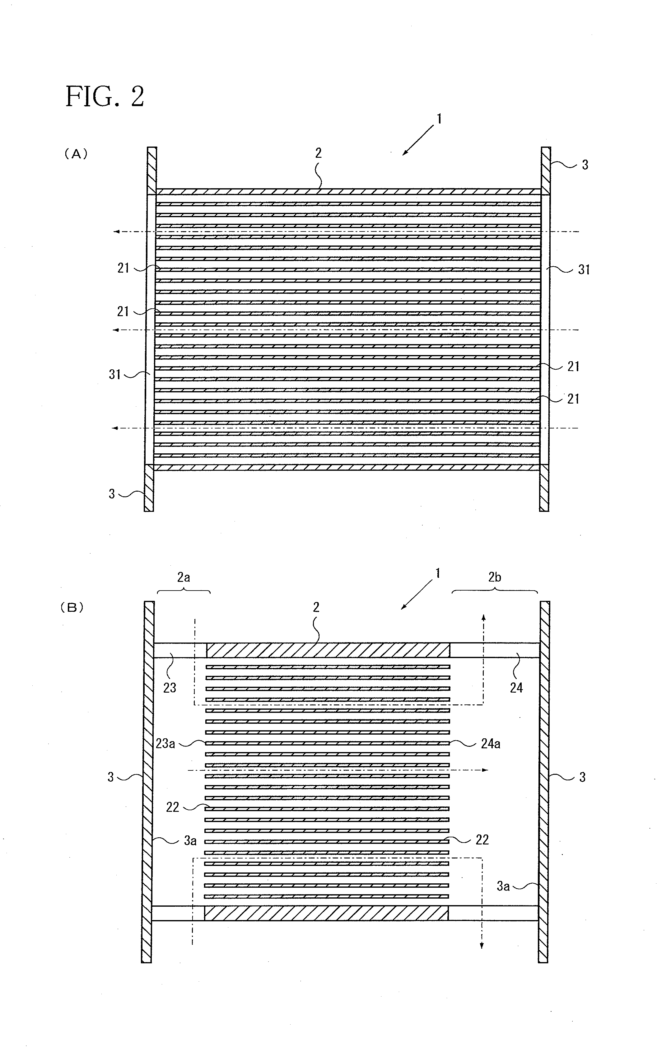
[0024]With reference to FIGS. 1 to 7, embodiments of the present invention will be described. FIG. 1 shows an embodiment of a ceramic heat exchanger according to the present invention, wherein FIG. 1(A) is a side view and FIG. 1(B) is a view as viewed in the direction of arrow B in FIG. 1(A). FIG. 2 shows cross-sectional views of the ceramic heat exchanger shown in FIG. 1(A), wherein FIG. 2(A) is a cross-sectional view along line SA-SA and FIG. 2(B) is a cross-sectional view along line SB-SB.

[0025]The ceramic heat exchanger 1 shown in FIGS. 1 and 2 is made of ceramic and intended to force a first medium and a second medium different in temperature (hereinafter referred to as “high-temperature medium” and “low-temperature medium”, respectively) to flow in opposite directions to transfer heat from the high-temperature medium to the low-temperature medium. The ceramic heat exchanger 1 comprises a body 2 having first channels 21 for the high-temperature medium to flow and second channel...


PUM

PropertyMeasurementUnit
heat resistanceaaaaaaaaaa
depths Daaaaaaaaaaa
particle sizeaaaaaaaaaa

Abstract

To provide a ceramic heat exchanger which has reduced joints, and thus, is easy to produce and less likely to leak and a method of producing same.The ceramic heat exchanger 1 according to the present invention comprises a body 2 having first channels 21 for a high-temperature medium to flow and second channels 22 for a low-temperature medium to flow, and lids 3 each having openings 31, joined to the body 2 at opposite ends 2a, 2b with the openings 31 connected to the first channels 21, the body 2 further having inlet channels 23 formed in a first channel 21 outlet-side end portion 2a to allow the low-temperature medium to enter the body at a side thereof and flow into the second channels 22, and outlet channels 24 formed in a first channel 21 inlet-side end portion 2b to allow the low-temperature medium to flow out of the second channels 22 and leave the body at the side thereof.

Description

TECHNICAL FIELD[0001]This invention relates to a ceramic heat exchanger and a method of producing same, and particularly, a ceramic micro-channel counter-flow heat exchanger and a method of producing same.BACKGROUND ART[0002]Ceramic is a material suitable for heat exchangers because of its light weight compared with metals and good thermal conductance. Particularly because of its good heat resistance, ceramic is regarded as a promising material for use in recovery of heat from high-temperature gases above 800° C., such as exhaust gases from gas turbines or others. Commonly used in high-temperature applications are metallic plate-fin heat exchangers, which exhibit high effectiveness, but have a drawback that complicated fin shapes lead to high costs. Ceramic is, however, a material difficult to work into complicated shapes because of its high hardness and brittleness. Heat exchangers using ceramic having such properties have already proposed, as seen in patent documents 1 to 3, for e...

Claims


Application Information

Patent Timeline
Patent Type & Authority Applications(United States)
IPC IPC(8): F28D7/00B21D53/02
CPCF28F7/02Y10T29/4935F28F21/04
Inventor MURAYAMA, MOTOHIDEISOMURA, KOUSUKETSURUZONO, SAZO
Owner IHI CORP
Why Eureka
Try Eureka