Low-temperature enthalpy spraying unit

A low-temperature unit technology, applied in the field of low-temperature enthalpy injection, can solve the problems of low unit reliability, many pipeline connections, and high manufacturing difficulty, and achieve the effects of reducing the risk of leakage, simplifying the pipeline system, and reducing manufacturing difficulty

Inactive Publication Date: 2016-11-23
GREE ELECTRIC APPLIANCES INC
View PDF12 Cites 0 Cited by
  • Summary
  • Abstract
  • Description
  • Claims
  • Application Information

AI Technical Summary

Problems solved by technology

[0004] The above-mentioned low-temperature enthalpy-injecting unit uses three-way joints and one-way valves to change the flow direction of the refrigerant. At least four three-way joints and four one-way valves are required, resulting in more parts and more joints of pipelines, and there is a greater risk of leakage , making the whole unit less reliable
[0005] In addition, changing the flow direction of the refrigerant through the three-way joint and the one-way valve makes the pipeline more complicated and makes the manufacturing of the whole unit more difficult.

Method used


Image

  • Low-temperature enthalpy spraying unit
  • Low-temperature enthalpy spraying unit
  • Low-temperature enthalpy spraying unit

Examples


Embodiment Construction

[0035] The following will clearly and completely describe the technical solutions in the embodiments of the present invention with reference to the accompanying drawings in the embodiments of the present invention. Obviously, the described embodiments are only some, not all, embodiments of the present invention. Based on the embodiments of the present invention, all other embodiments obtained by persons of ordinary skill in the art without making creative efforts belong to the protection scope of the present invention.

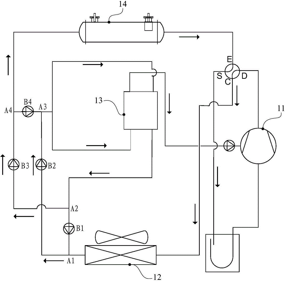
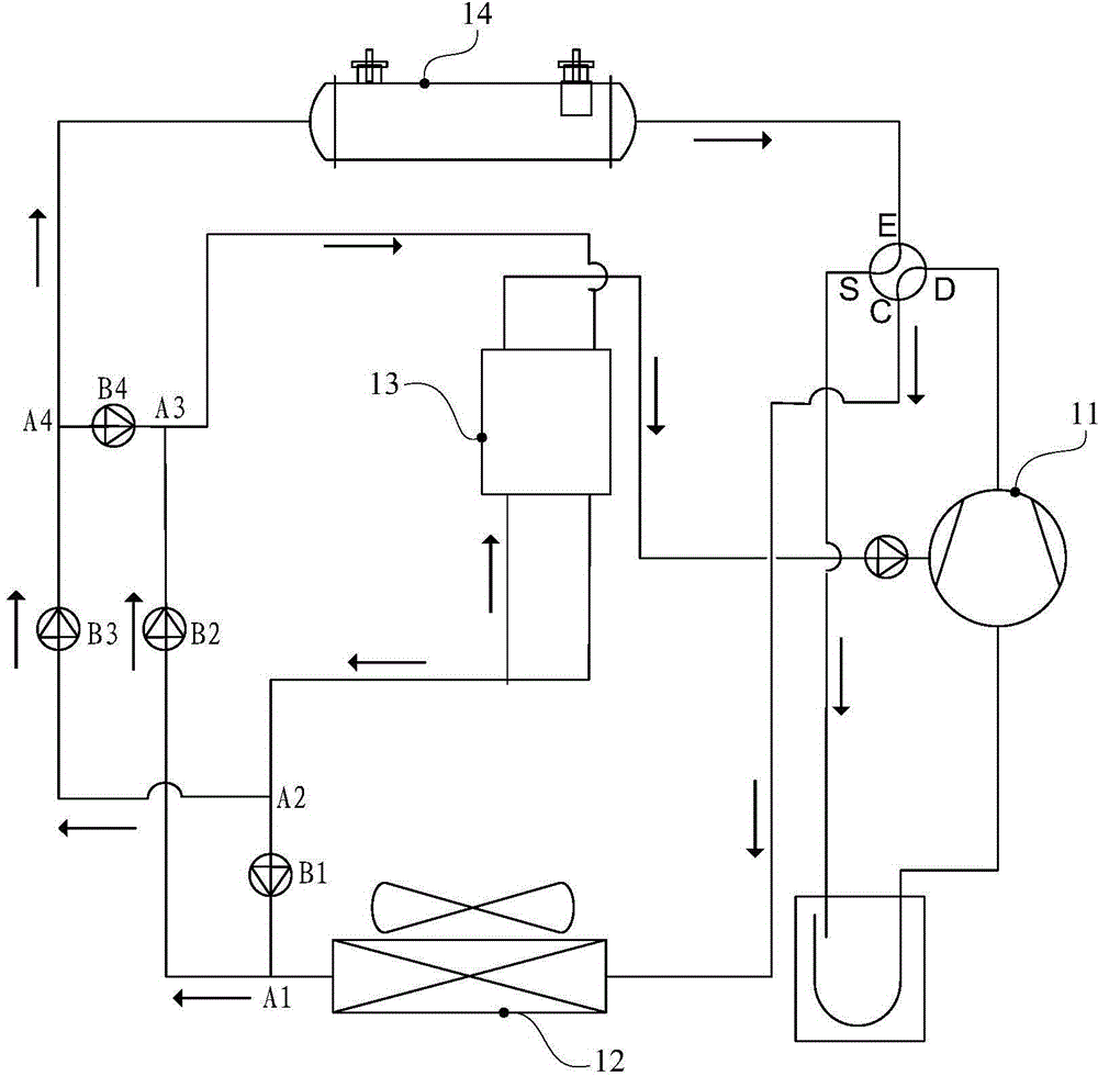
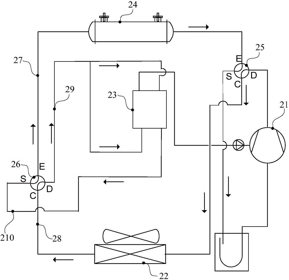
[0036] The low-temperature enthalpy injection unit provided by the embodiment of the present invention includes: a compressor 21, an indoor heat exchanger 24, an outdoor heat exchanger 22, an economizer 23, an enthalpy injection four-way valve 26, a first pipeline 27, a second pipeline 28, a The third pipe 29 and the fourth pipe 210 .

[0037] Wherein, the first inlet of the economizer 23 communicates with the liquid outlet of the economizer 23 , the second in...


PUM


Abstract

The invention discloses a low-temperature enthalpy spraying unit. The low-temperature enthalpy spraying unit comprises a compressor, an indoor heat exchanger, an outdoor heat exchanger, an economizer, a first pipeline, a second pipeline, a third pipeline, a fourth pipeline and an enthalpy spraying reversing valve, wherein the indoor heat exchanger and the outdoor heat exchanger communicate with the compressor; an air outlet of the economizer communicates with an air supply opening of the compressor; the first pipeline communicates with the indoor heat exchanger; the second pipeline communicates with the outdoor heat exchanger; the third pipeline communicates with a first inlet of the economizer; the fourth pipeline communicates with a liquid outlet of the economizer; and the enthalpy spraying reversing valve can enable the first pipeline to communicate with the fourth pipeline and enable the second pipeline to communicate with the third pipeline simultaneously, and the enthalpy spraying reversing valve can also enable the first pipeline to communicate with the third pipeline and enable the second pipeline to communicate with the forth pipeline simultaneously. A second inlet of the economizer communicates with the third pipeline or the fourth pipeline. The first inlet communicates with the liquid outlet. The second inlet communicates with the air outlet. According to the low-temperature enthalpy spraying unit, the number of parts and components is decreased, accordingly, the number of joints of the pipelines is effectively decreased, the leakage flow risks are reduced, and the reliability of the whole unit is improved; and a pipeline system is simplified, and the manufacturing difficulty of the whole unit is lowered.

Description

technical field [0001] The invention relates to the technical field of low-temperature enthalpy injection, and more specifically, relates to a low-temperature enthalpy injection unit. Background technique [0002] Heat pump units and air conditioning units often use low-temperature enthalpy injection technology to improve energy efficiency. For the low-temperature enthalpy injection unit, the high-pressure liquid refrigerant flowing out of the condenser enters the economizer in two ways, and then flows out in two ways, one into the evaporator and the other into the compressor. [0003] At present, the refrigerant flow direction is changed through a three-way joint and a one-way valve. Specifically, such as figure 1 with figure 2 As shown, during refrigeration, the refrigerant reaches the three-way joint A1, the refrigerant reaches the three-way joint A3 through the action of the one-way valve B1 and the one-way valve B2, and the refrigerant flows to the economizer 13 thr...

Claims


Application Information

Patent Timeline
Patent Type & Authority Applications(China)
IPC IPC(8): F25B13/00F25B41/04F25B49/02F25B41/20
Inventor 吴呈松郑伟平林海东张龙爱孙思张恩泉魏峰
Owner GREE ELECTRIC APPLIANCES INC
Why Eureka
Try Eureka