Apparatus and Method for Determining Shape of End of Welding Bead

Inactive Publication Date: 2012-03-01
SUZUKI MOTOR CORP
View PDF17 Cites 59 Cited by
  • Summary
  • Abstract
  • Description
  • Claims
  • Application Information

AI Technical Summary

Benefits of technology

[0035]In addition, according to the method for determining the shape of an end of a welding bead in the present invention, the process for recognizing the bead region includes: determining, as bead region candidates, regions having luminance equal to or greater than a predetermined region recognition threshold within the image; and determining whether each of the bead region candidates is the bead region based on an aspect ratio of the bead region candidates. Accordingly, the bead region is recognized by a simple process such as obtaining the aspect ratio, thereby enabling high-speed recognition processing.
[0036]In addition, according to the method for determining the shape of an end of a welding bead in the present invention, the process for determining whether the shape of the end of the bead region is convex or concave includes: calculating a representative point of the bead region; calculating a center position of the end of the bead region; calculating an intermediate point between the representative point of the bead region and the center position of the end of the bead region; calculating two straight lines which extend parallel on both sides of the line connecting the center position and the intermediate point, and intersect with the periphery of the end of the bead region; and calculating intersection points between the two straight lines and the periphery of the end, calculating a degree of

Problems solved by technology

For this reason, there is a problem that a weld defect at the end of the bead region cannot be determined with the same determination method as that used during the welding process.
Moreover, the method disclosed in Patent Document 2 also requires an apparatus for emitting

Method used


Image

  • Apparatus and Method for Determining Shape of End of Welding Bead
  • Apparatus and Method for Determining Shape of End of Welding Bead
  • Apparatus and Method for Determining Shape of End of Welding Bead

Examples


Embodiment Construction

[0051]With reference to the drawings, description is given below of an apparatus and a method for determining the shape of an end of a welding bead part (hereinafter referred to as the “bead”) according to an embodiment of the present invention.

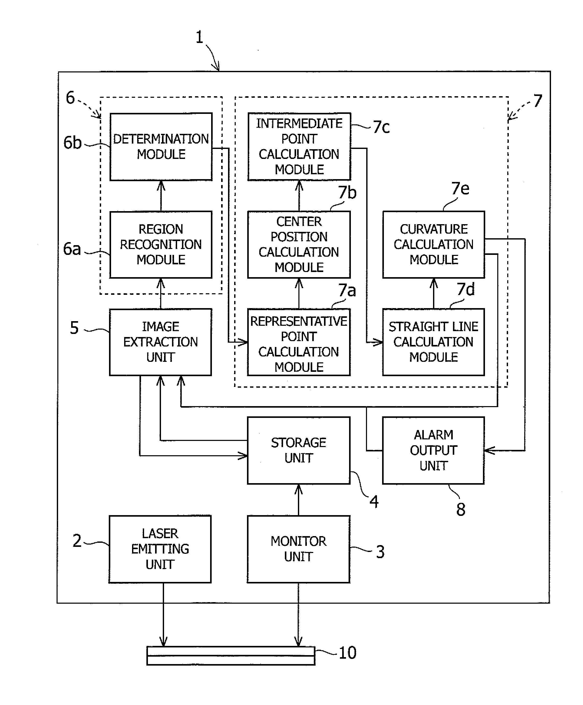
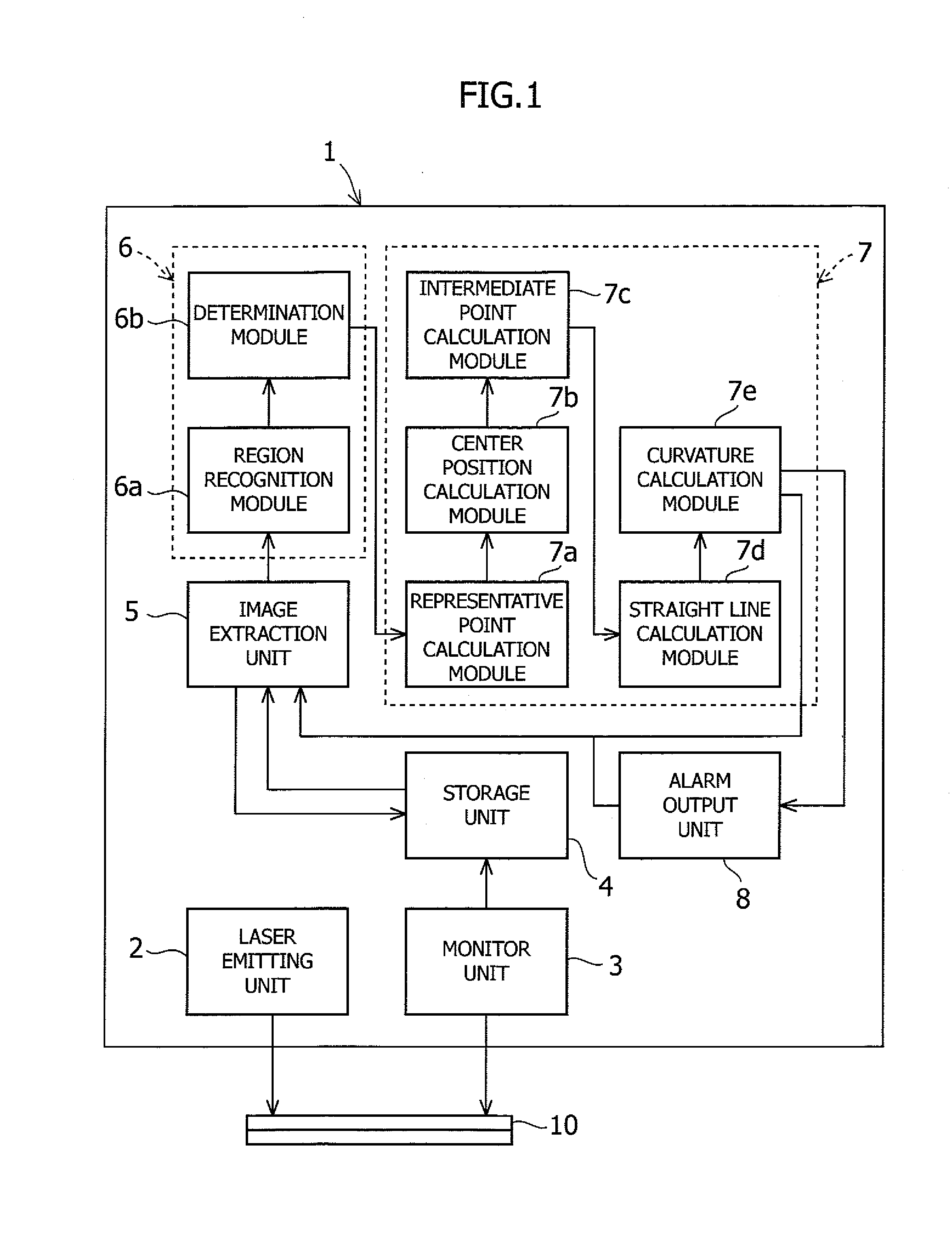
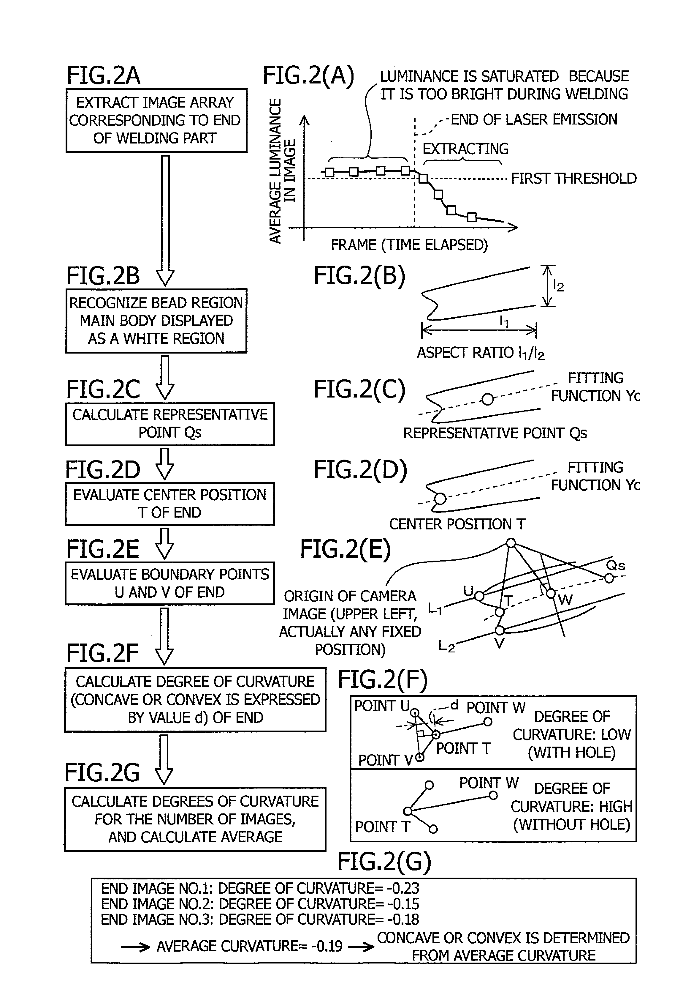
[0052]FIG. 1 is a block diagram showing a configuration of an apparatus for determining the shape of an end of a welding bead according to an embodiment of the present invention, and FIG. 2 is a diagram showing a procedure for determining the shape of the end of a welding bead region. FIG. 3 is a diagram showing a configuration of a monitor unit according to the embodiment of the present invention, and an image extracting process performed by an image extraction unit.

[0053]As shown in FIG. 1, an apparatus 1 for determining the shape of the end of the bead according to this embodiment is an apparatus used for lap welding weld materials 10. The apparatus 1 includes a laser emitting unit 2, a monitor unit 3, a storage unit 4, an image extraction...


PUM

PropertyMeasurementUnit
Shapeaaaaaaaaaa
Luminanceaaaaaaaaaa
Aspect ratioaaaaaaaaaa

Abstract

An apparatus 1 of the present invention includes a laser emitting unit 2, a monitor unit 3, a storage unit 4, an image extraction unit 5, a bead recognition unit 6, and a bead shape determination unit 7. The bead shape determination unit 7 is configured to calculate the position of the end of a bead region based on the bead region recognized by the bead recognition unit 6, and to determine whether the shape of the end of the bead region is convex or concave in the extending direction of the bead region.

Description

CROSS-REFERENCE TO RELATED APPLICATIONS[0001]This application claims the benefit of the filing date of Japanese Patent Application No. 2010-192129 filed Aug. 30, 2010, the entire disclosure of which is hereby incorporated herein by reference.BACKGROUND OF THE INVENTION[0002]1. Field of the Invention[0003]The present invention relates to an apparatus and to a method for determining the shape of an end of a welding bead (welding part) formed by irradiating a welding material with a welding laser. More specifically, the present invention relates to an algorithm to, in laser lap welding, capture an image of an end of a welding bead with a high-speed camera and to determine whether there is a hole defect at the end of the welding bead based on the captured image in a very short period of time immediately after the welding and before thermoluminescence from the metal ends disappears.[0004]2. Description of Related Art[0005]There has heretofore been proposed a method for detecting a weld d...

Claims


Application Information

Patent Timeline
IPC IPC(8): B23K26/03B23K26/00B23K26/21B23K31/00G01B11/24
CPCB23K26/032B23K31/125B23K26/246B23K26/244
Inventor ISHIDA, HIDENOBUOZAWA, NAOKIHAGIHARA, TSUKASAUSUI, SHUICHI
Owner SUZUKI MOTOR CORP
Why Eureka
Try Eureka